To keep pace with the fast changing requirements of the optics market, ModuleWorks has added several new features to its ultra-precision machining core. These new features advance the overall strategy of combining conventional CAM machining patterns like roughing, drilling and chamfering with the needs of ultra-precision machining.
The input data for ultra-precision machining are different to those in standard CAD/CAM systems. Optical features are often defined by formulas, polynomials and point clouds. ModuleWorks accepts a mixture of these different data types as input for toolpath generation and now also accepts so-called secondary drive surfaces that provide optional control of the tool orientation motion. This new feature smooths out vibrations and orientation changes for improved multi-axis turning and milling of complex workpieces.
A spiral morph pattern has been developed for manufacturing non-rotational symmetrical molds for lenses. The morph pattern delivers enhanced precision by generating a continuous toolpath without abrupt changes in the tool direction.
Furthermore, new application-driven projection methods ensure optimal pattern distribution onto surfaces for manufacturing parts within required form and positional tolerances. In addition, new projection methods enable inside and outside diamond turning.
New Ultra-Precision Machining Features
Spiral Morph Pattern
This new toolpath pattern enhances the precision of non-rotational symmetrical parts. This feature is in high demand for manufacturing molds for elliptical lenses where a continuous toolpath from the outer elliptical contour to the circular center of the parts is needed. The spiral morph pattern creates a spiral toolpath which morphs the elliptic outer contour into a circular one in the center. Users benefit from a continuous toolpath without abrupt change in the tool direction, which enhances precision.
The algorithm interpolates between the outer and inner input curves, which can both be arbitrarily formed. You can also control other parameters such as the cutting direction and the distance between adjacent toolpaths (step-over).
Point Data Import
ModuleWorks provides new types of toolpath-generation based on Point Data Import which come from measurement devices like touch probes, interferometer or are generated by software systems like Matlab.
Since optical free-form surfaces are often described by formulae, NURBS surfaces or also point
data, modern CAM-systems for Ultra Precision Machining must support all these different sorts of surface description. In terms of Point Data, new data formats are now supported. Besides the already supported import of xyz-data, the ModuleWorks core now support the import of:
- Point profile allows the input of a profile which means points in xz-plane. It can be imported as xz- or txt-file. A point with x=0 will generate a closed surface in the center.
- Radial point grid allows the input of radial point grids which are xzc-profiles. Radial points can be imported as xzc- or txt-file format. C is the angle in degrees which is measured counterclockwise in workpiece coordinate system. Angle step or radial point distance can be irregular. Every point must have a unique position.
Users can combine various kinds of surface inputs together and tailor their toolpaths. A typical example can be to first calculate a toolpath using point cloud or parametric surface. The user can tailor this toolpath in a second step by using NURBS surface to specify which areas of the part should not be machined. Additionally a secondary surface can be chosen to specify the orientation of the cutting tool during machining.
Point and Line Projection
New projection methods are now available for projecting toolpath patterns onto the surface of a part.
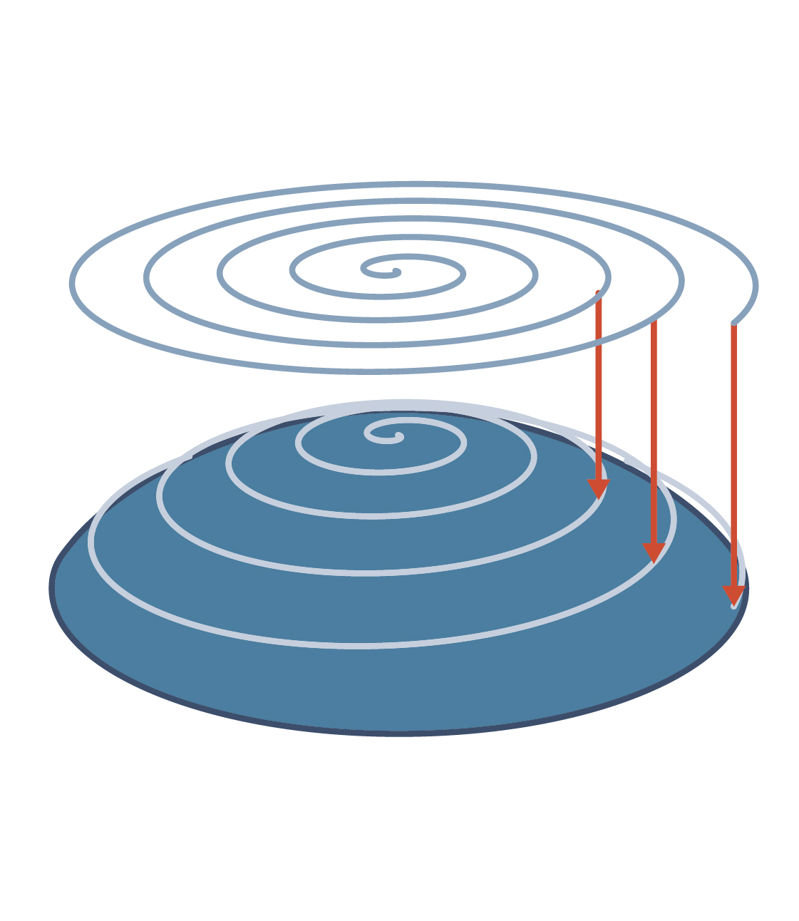
Standard methods use Z-axis projection to project a pattern from top to bottom onto a surface, but z-axis projection does not deliver appropriate toolpaths for all types of part. ModuleWorks has developed application-driven solutions that complement the Z-axis projection with two new methods. Each method is appropriate for specific part shapes. The three projection types are:
- Z-Axis Projection: the standard projection method. The toolpath pattern is generated in the xy-plane and projected along the z-axis onto the surface.
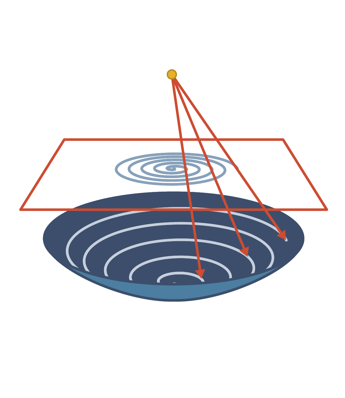
- Point Projection: The toolpath pattern is generated on a plane which is parallel to the xy-plane at a specified height and then projected towards (or away) from a point on the z-axis at a given height. Its preferred application is, for example, for strongly curved lens surfaces which are not completely covered by Z-axis projection. Point projection can also be combined with the spiral morph pattern to manufacture asymmetric molds such as D-segments.
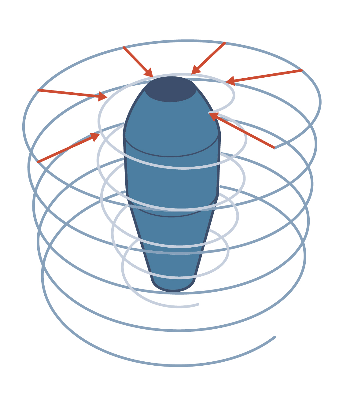
- Line Projection: A helix toolpath pattern (axis on the z-axis) is generated and radially projected towards (or away) from the z-axis. It is predominantly used for tube-shaped parts. It generates a revolving pattern which can cover either the inner or outer surface. A typical application area is turning vertical walls on an asymmetric die using inside and outside diamond turning.