| |
ModuleWorks, the leading supplier of CAD/CAM software components for machining and simulation, announces the release of Dental Framework version 2017 with new, intelligent features for chair-side applications and complex dental indications.
| ModuleWorks Dental Framework is a dental CAM plug-and-play product that performs advanced toolpath calculations and outputs the corresponding NC file for dental CNC machines. It uses verified and configurable machining templates in the form of xml scripts for efficient and flexible implementation and contains a complete toolset library for manufacturing a wide spectrum of dental indications. The integrated CAM-engine, which is used for the toolpath calculations, provides high performance 3-Axis, 4-Axis, and 5-Axis CAM features for enhanced machining strategies in dental milling and grinding (chair-side) applications. |  |
ModuleWorks Dental Frameworks 2017 offers new, intelligent high-performance algorithms for chair-side grinding applications. The core CAM features for milling applications have also been enhanced to increase the efficiency and quality of machining operations for complex dental indications, including indications with deep undercuts.
Grinding (chair-side) applications
Adaptive roughing
By ensuring the cutting conditions remain almost constant, the adaptive roughing strategy has significant advantages over conventional constant offset roughing. Adaptive roughing avoids full-width cuts by constantly measuring the engagement volume of the tool with the material and gradually removing material from the remaining stock. It guarantees a stable load on the tool, which accelerates material removal at higher feed rates and reduces the overall machining time.
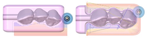
Fig 1. Parallel constant offset roughing toolpath (left), adaptive-roughing toolpath (right)
Adaptive rouging can be used for grinding bridges, crowns, inlays, and veneer indications.
Support for multicore CPU calculation accelerates toolpath generation.
Constant-cusp with intelligent “adaptive step over”
The constant-cusp pattern continuously analyzes the remaining stock in front and adapts the step over to ensure the tool engagement with the stock is always the most efficient and appropriate for the particular grinding application. Larger step over values reduces the machining time, finer step over values optimize the cutting conditions and prolong tool-life.
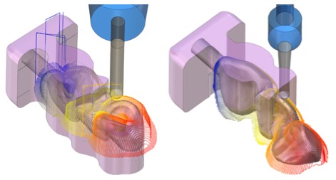
Fig 2. Constant-cusp toolpath with adaptive step over. Cavity side (left), occlusal side (right)
The zigzag cutting approach from the front of the blank to the pin side ensures strong material support on the pin side while machining. This prevents pin breakage during grinding.
Constant-cusp with adaptive step over can be used for grinding bridges, crowns, inlays, and veneer indications.
Milling applications
Constant-cusp with “3D-silhouette curve” and “flip step over”
The 3D-silhouette curve, which can be understood as the equator line of dental construction, can be used as a reference curve for splitting the constant-cusp finishing operations from the occlusal and cavity sides. This approach ensures minimal overlap of both operations and reduces the total toolpath length by up to 30% compared to the classic wing-surface approach.
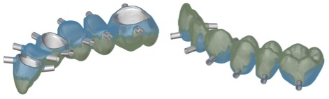
Fig 3. Constant-cusp finishing toolpath with 3D-silhouette curve. Cavity view (left), occlusal view (right)
The flip step over feature changes the cutting direction when the 3D-offset toolpath, referenced from the margin curves, reaches the 3D-silhouette curve. This minimizes the number of trimmed links to produce a more efficient machining process.
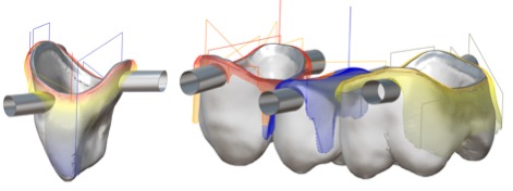
Fig 4. Flip step over feature, crown (left), bridge (right)
3+2-Axis automatic undercuts (AU) with “processing from both sides”
The 3+2-Axis automatic undercut strategy automatically detects the undercut areas from the top and bottom without any user input and then machines each undercut region from the best approachable machining angle. This can be processed in two different cycles, from the top and the bottom, to machine all undercuts on each side. The “process from both sides” feature allows you to combine both cycles into one. It considers the machining angles from both sides to find the best approach angle. This ensures the undercut region is machined from the best approachable machining angle, which could be from either the top or bottom.
To complete the operation, the toolpaths are coupled together from both sides via a cylindrical link around the rotary axis of the machine, which goes beyond the blank and the blank-holder.
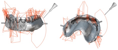
Fig 5. Denture 3+2-Axis automatic undercut toolpath. Denture occlusal side (left), basal side (right)
Processing from both sides prevents redundant overlap machining from the counter side, which can reduce the undercut machining time by 30-50% depending on the geometry.
3-Axis constant-cusp with “exclude undercuts” and “3+2-Axis AU”
When performing a 3-Axis overall finishing cycle, the tool does not remove any material as it passes through the undercut regions. This redundant air milling can account for 10-20% of the entire operation when machining dental indications with wide undercut areas. The exclude undercut feature removes the redundant toolpath segments and adjusts the cutting order to minimize the number of resulting links.
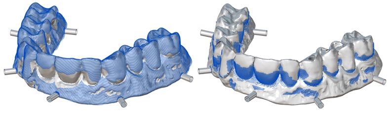
Fig 6. Implant-bridge 3-Axis constant-cusp toolpath with exclude undercut (left) and 3+2-Axis automatic undercut (right)
The undercut areas are processed in a separate, dedicated cycle for undercut machining. 3+2-Axis AU or 5-Axis AU strategies from the ModuleWorks Dental CAM portfolio can be used for this.
5-Axis geodesic
This strategy is for machining complex 3D dental constructions with toolpaths that have an overall constant step over on both the shallow and steep areas as well as undercut areas
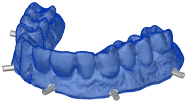
Fig 7. 5-Axis geodesic toolpath applied to an implant bridge
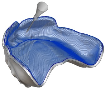
Fig 8. 5-Axis geodesic toolpath applied to a denture
A geodesic toolpath has significant benefits for pre-mill abutment manufacturing. Unlike the common parallel projected zigzag pattern, which often leads to an unsmooth finish on steep surfaces or conservative step over values and long machining times, geodesics can generate a 3D equidistant toolpath, even on steep emergence profiles and dint surfaces.
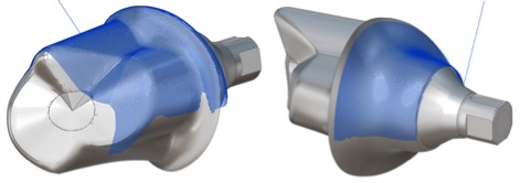
Fig 9. Geodesic toolpath on pre-mill abutment
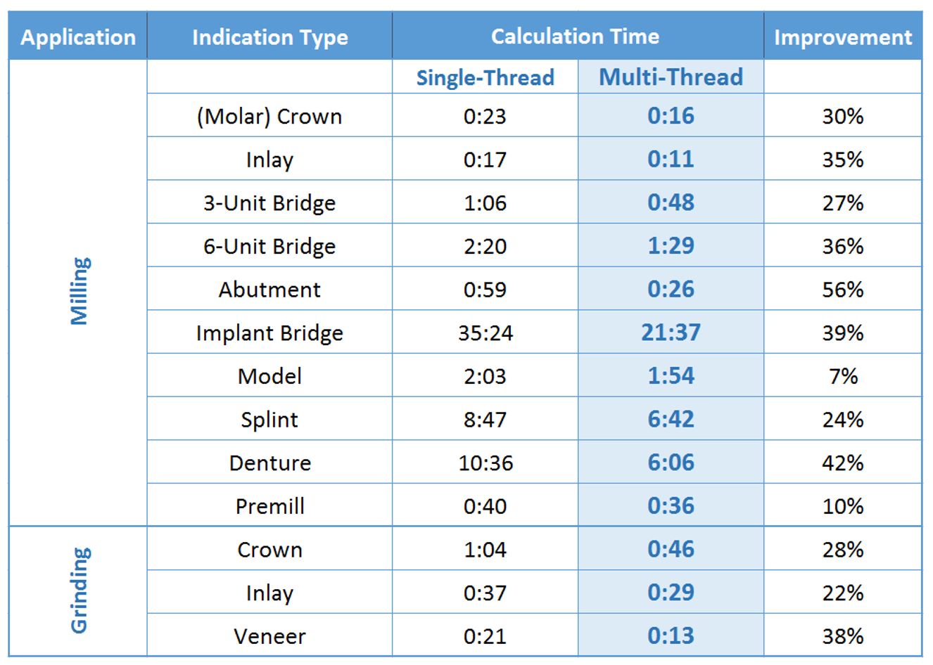
Calculation performance and multicore processing
The high-performance integrated Dental Framework CAM-engine makes ModuleWorks Dental CAM one of the fastest Dental CAM solutions on the market. Multicore processing accelerates toolpath calculation by up to 56%. This is especially important for new indications with complex geometries such as implant bridges, dentures and splints which would otherwise require longer processing times.
More details related to these latest achievements will be presented at:
– IDS 2017 Speakers’ corner (ModuleWorks Dental CAM) .
– IDS 2017 Hall 4.2 Booth: M030 N031
If you require any further information, please send an email to: support-dental@moduleworks.com
About ModuleWorks
ModuleWorks is a software component provider for the CAD/CAM industry. ModuleWorks’ expertise in toolpath creation and simulation is recognized throughout the CAM industry and its software components and development services are used by the majority of the leading CAM vendors for industry focused solutions across diverse business sectors. ModuleWorks Dental Framework brings these benefits to the dental CAM industry. Already used by many leading dental systems, the advanced 3-Axis, 4-Axis, 5-Axis and simulation technology provides rapid toolpath calculation times, fast machining times and high quality results.