Challenge: Rotary finishing for cylindrical or conical surfaces traditionally requires the milling head to tilt at the same angle as the defined cone angle in order to detect the floor and apply the toolpath. This can be limiting and cumbersome, especially for machine tools without a B-axis.
Solution: With this enhancement, it is now possible to define the angle for floor detection while keeping the milling head stationary or tilting it to a completely different angle. This enables more versatile and efficient machining of angled floors.
Benefits: This feature enhances flexibility by allowing users to machine angled floors in a 4-axis mill-turn machine or define specific angles without tilting the milling head. It improves precision by ensuring accurate toolpaths on conical surfaces, resulting in high quality finishing.
Special Parts | Multiblade
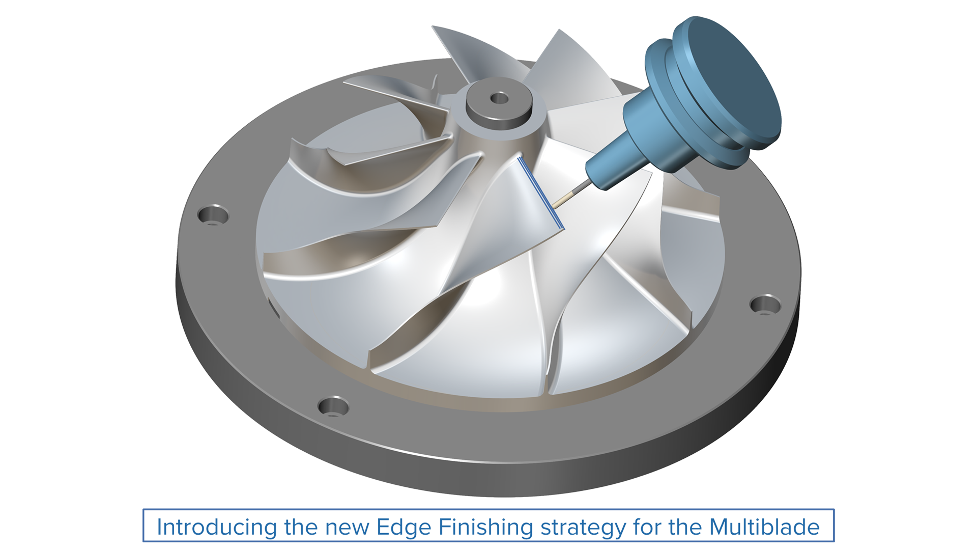
Edge Finishing
Challenge: Users want to avoid the tool rubbing against the leading edge because it is thin and may overheat due to tilting and machine motion. To address this, an extension is applied, leaving offset material to be removed later.
Solution: This strategy drives the tool longitudinally along the edge, effectively removing the extra material left from the previous operation without causing damage to the thin leading edge.
Benefits: This toolpath matches the user process and allows the part to be finished with the required surface quality and material integrity. It ensures that the thin leading edge is not damaged, maintaining the integrity and quality of the finished part.
Special Parts | Multiblade
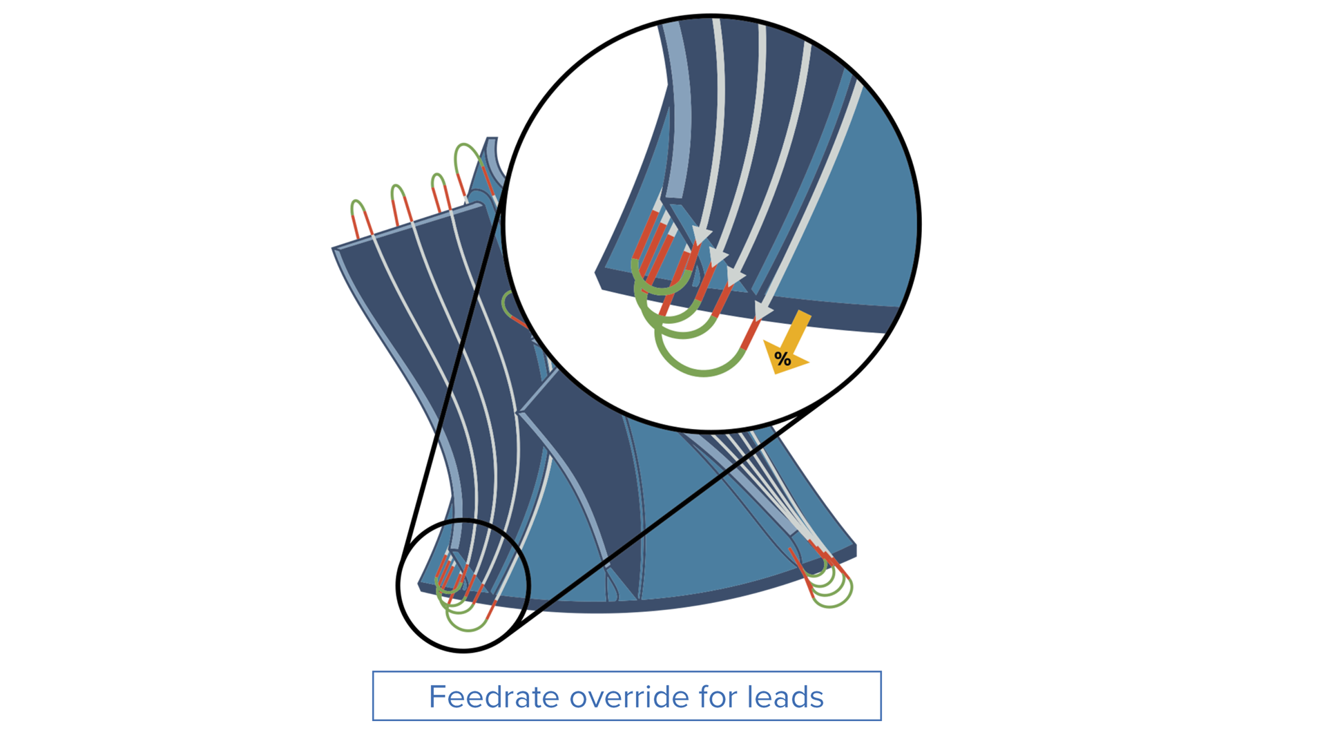
Feedrate Override for Leads
Challenge: Until now, users have been limited to using feedrate overrides only for links, extensions and the actual toolpath.
Solution: Now, there is an option to set the feedrate override for lead-in and lead-out moves as a percentage of the actual toolpath feed rate.
Benefits: This feature ensures the tool enters and exits the workpiece smoothly, resulting in a better surface finish and improved tool life.
3-Axis
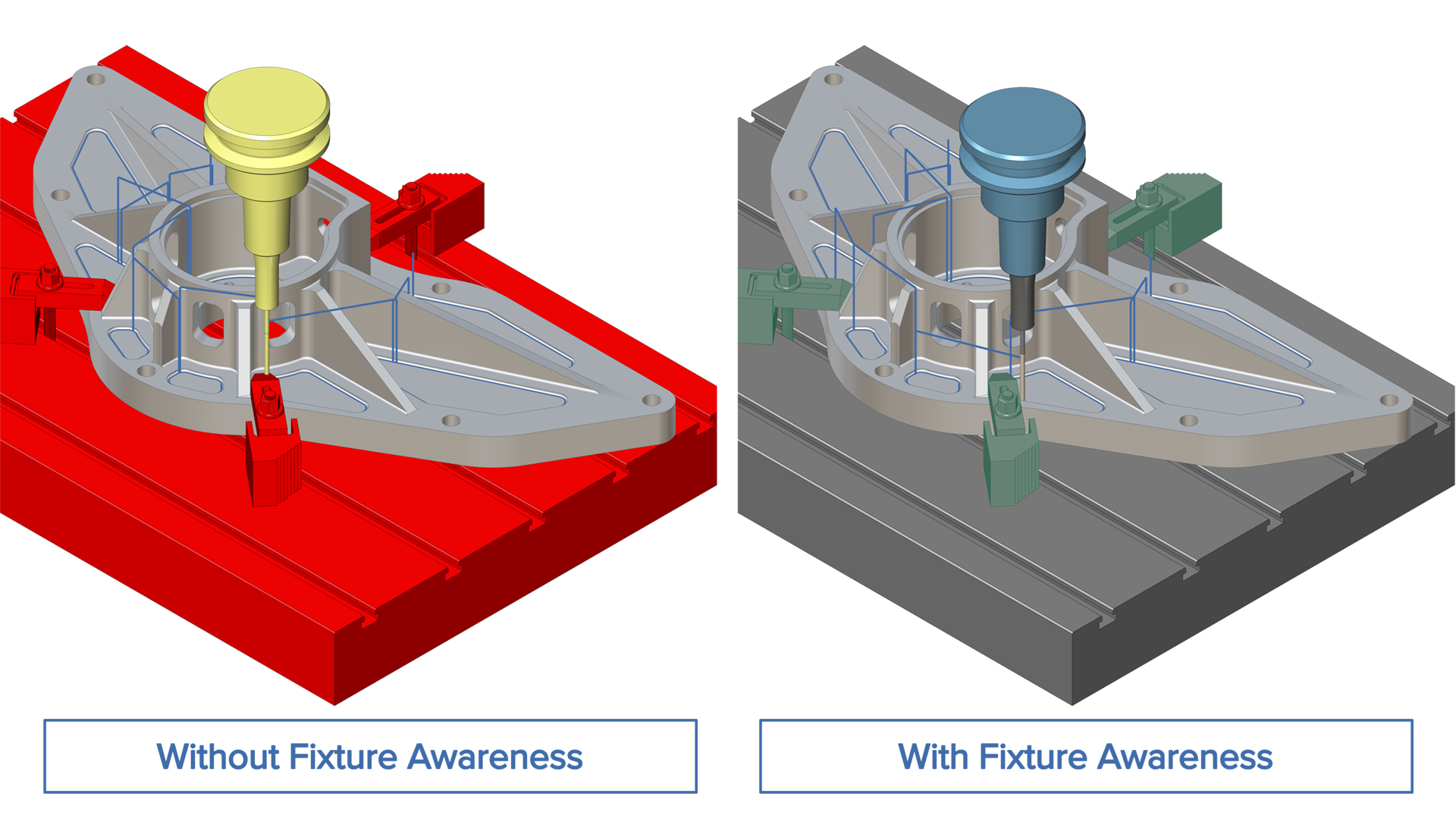
Fixture Awareness for Pencil Machining
Challenge: If fixtures cannot be defined for the toolpath calculation to prevent collisions, manual containments must be created to achieve a gouge-free result.
Solution: Fixtures can now be defined as surfaces, solids, or mesh bodies for pencil machining. This enables the toolpath calculation to automatically prevent collisions by avoiding contact with the fixtures.
Benefits: This greatly improves the usability of the pencil machining strategy. By considering fixtures during the toolpath calculation and avoiding additional containment generation, programming time is reduced. The generated toolpath is also completely safe.
3-Axis
Links Between Regions
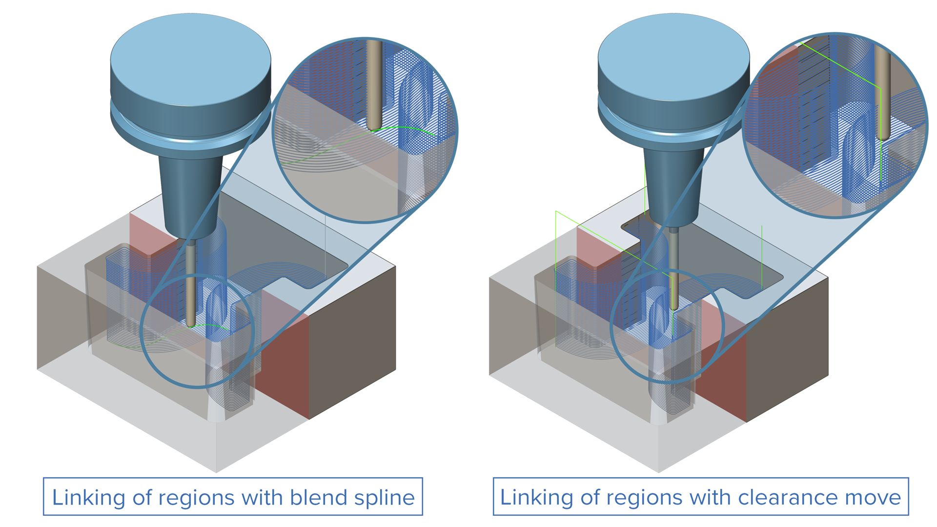
Challenge: Previously, for Constant Z-related patterns, independent areas were sometimes generated where no suitable linking option was available. This resulted in undesired behavior or required the user to choose an overly conservative linking option.
Solution: An additional linking option for regions has been added, providing more refined control over the linking behaviour.
Benefits: With this feature, users can easily handle complex linking scenarios without compromising on efficiency.
3-Axis
“Blend Along Distance” for Constant Z and Combo Cycles
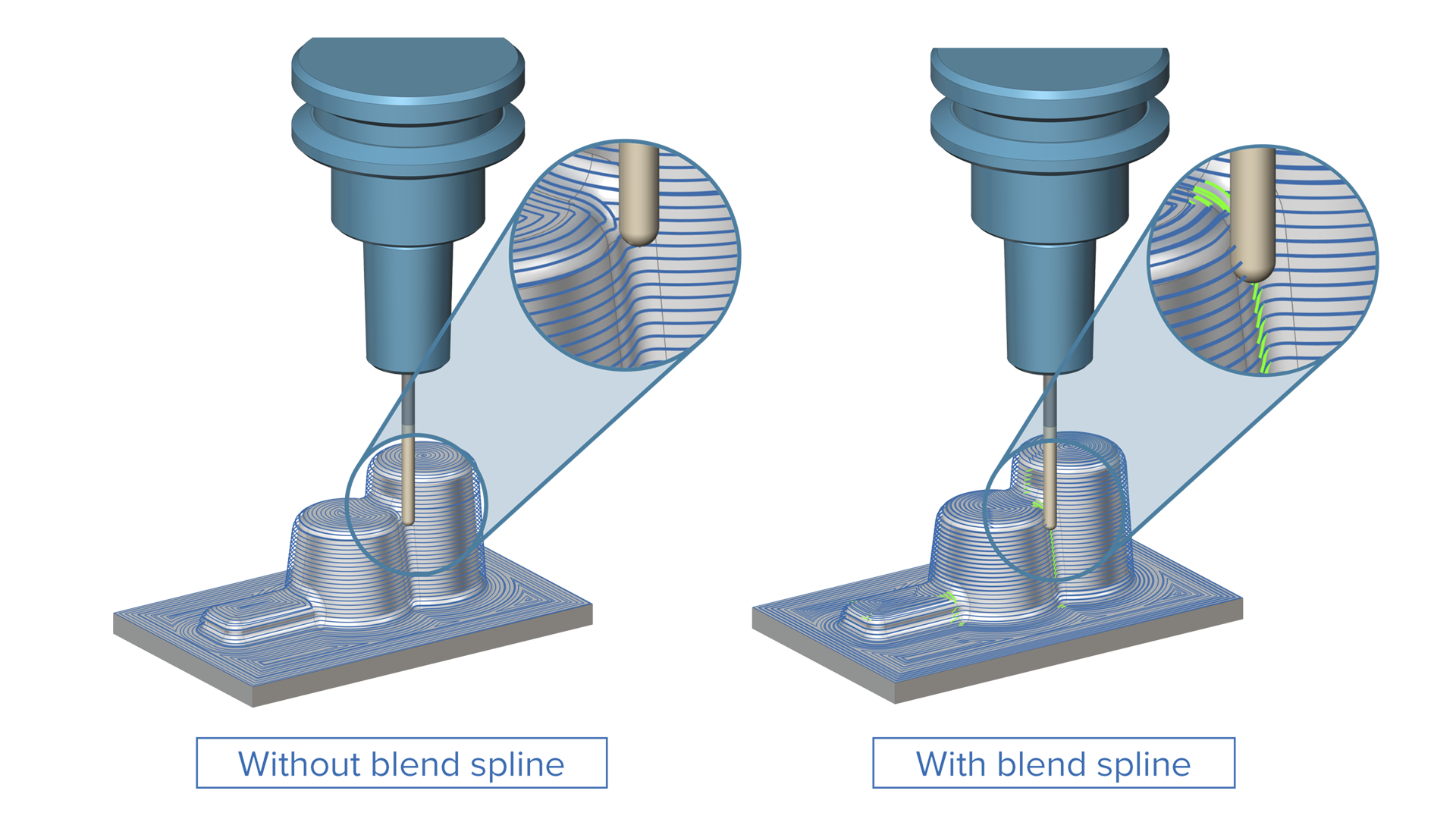
Challenge: On complex parts, the full spiral option can cause the toolpath pattern to collapse in several areas, leading to unnecessary retracts. Additionally, it generates a more complex pattern when handling complex topologies.
Solution: With this new feature, users can specify the distance of a blend move, which minimizes the number of spiral moves.
Benefits: This feature ensures smoother transitions between the passes. Fewer retracts also improve the consistency of the toolpath.
Turning / Prime Turning
Extend Straight Passes for Adaptive Turning
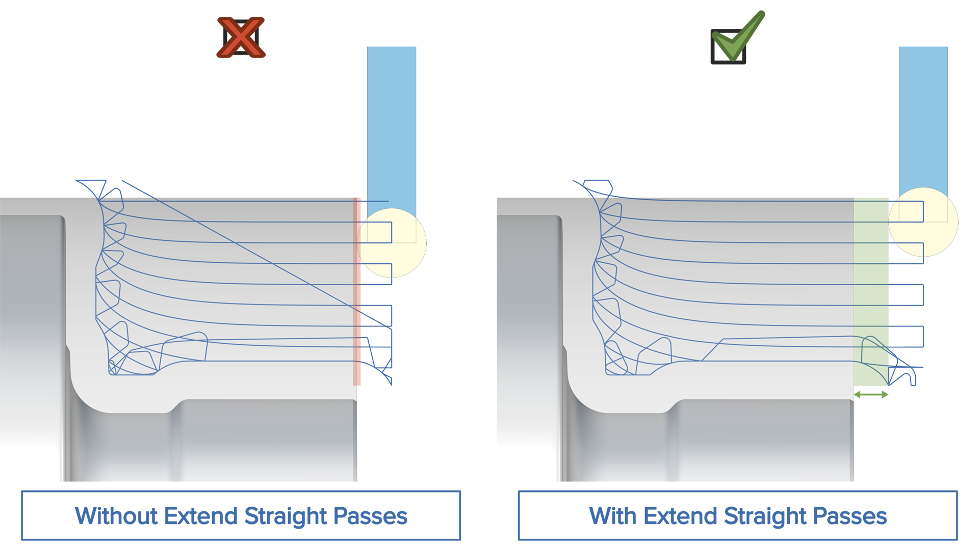
Challenge: During adaptive turning operations, the insert rubs against the stock when linking the straight passes, which is undesirable.
Solution: The adaptive straight passes can now be extended beyond their initial limits using the new ‘Extend straight passes’ option.
Benefits: This feature generates cleaner cutting moves by extending the adaptive straight passes. As a result, linking is performed at a safe distance, which improves insert life.
Multi-Axis Additive | Fused Deposition Modeling
Corner Detection
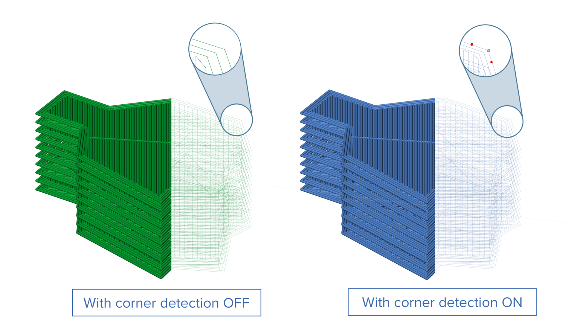
Challenge: Sharp corners present a challenge in FDM (Fused Deposition Modeling), as abrupt changes in direction can reduce printing speed, resulting in defects on the printed part or even disrupting the process.
Solution: Now, based on a corner threshold angle, corners are detected and marked as a corner. Additionally, a point is added before and after the corner, allowing users to react and adjust parameters such as the extrusion rates or feedrates.
Benefits: This new feature prevents marks from occuring during the milling processes. It also ensures a stable additive process without damaging the part.
Simulation
Simulation SDK |
CNC Simulation
Asynchronous Rendering
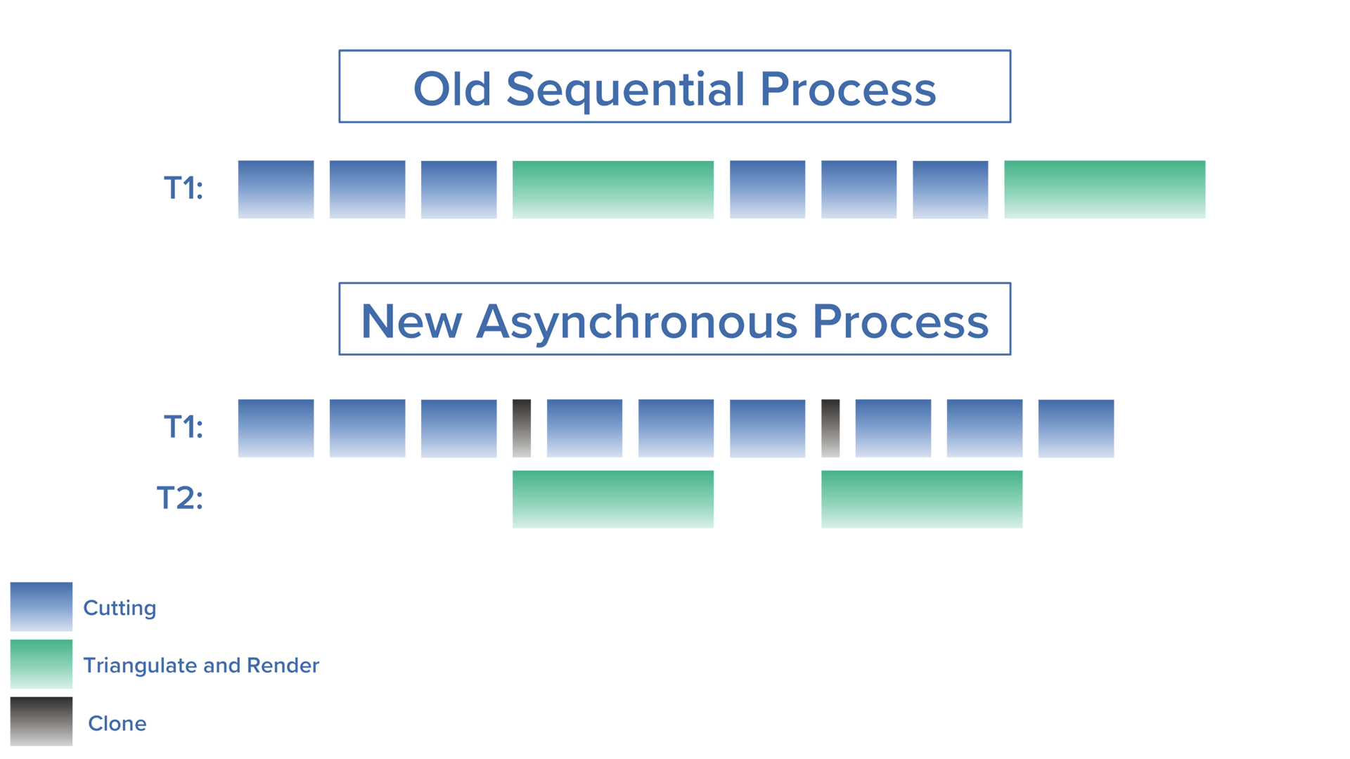
Challenge: Rendering highly complex in-process stocks can be computationally intensive, affecting the responsiveness of the machine simulation.
Solution: Asynchronous rendering uses a separate thread to triangulate and render the in-process stock, independent of the simulation thread.
Benefits: This improvement accelerates simulation in play mode by eliminating wait times for in-process stock rendering.
Simulation SDK |
Cutting Simulation
Optimized GPU-Accelerated Simulation in Play Mode
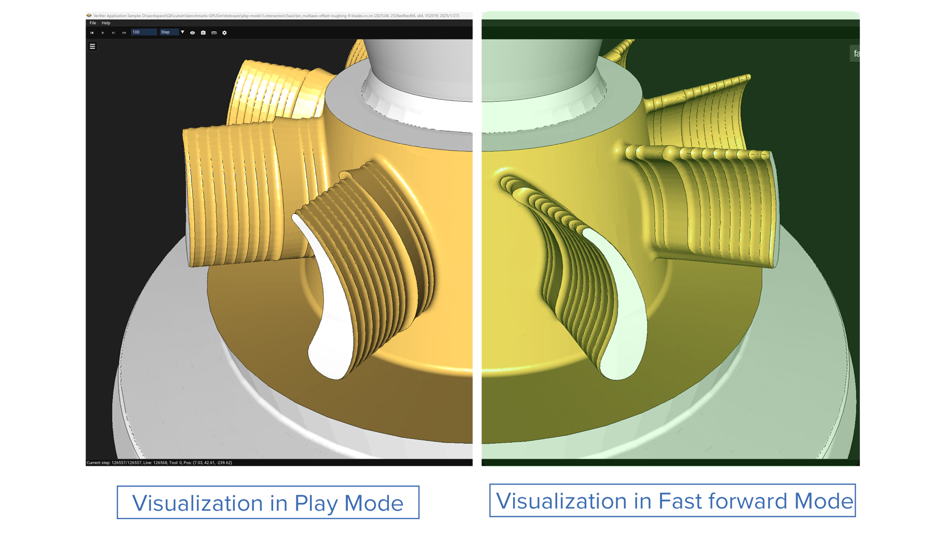
Challenge: Play-mode simulations were not optimized with GPU acceleration, resulting in inefficient visualization of the machining progress.
Solution: This release optimizes GPU-accelerated material removal by enabling efficient batch processing of toolpath moves while retaining the stock model in GPU memory.
Benefits: This enhancement reduces simulation overhead and speeds up progressive play-mode simulations by utilizing the GPU.
Simulation Systems | NC Editor
Support for Polar Coordinate Interpolation Mode G12.1/G13.1
Challenge: Previously, NC Editor did not support polar coordinate interpolation mode G12.1/G13.1.
Solution: The implementation of G12.1/G13.1 in NC Editor allows it to interpret and convert commands programmed in a Cartesian coordinate system into the corresponding movements of a linear axis and a rotary axis.
Benefits: This feature enables users to overcome limitations in linear axis results and make optimal use of the machine kinematics.
Simulation Systems | NC Editor
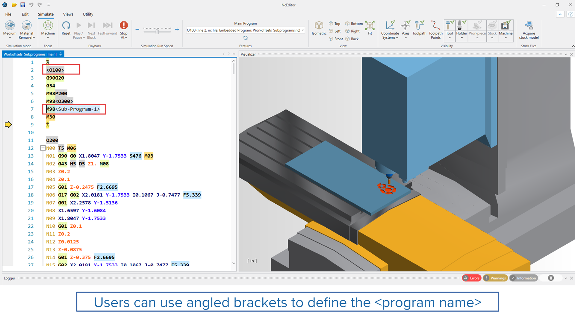
Support for Program Name Defined by Angled Brackets
Challenge: Previously, NC Editor only supported program numbers, limiting its ability to work with Fanuc control systems where program names can be specified using angled brackets.
Solution: This new feature enables NC Editor to recognize and interpret program names defined by angled brackets, ensuring seamless integration with Fanuc control systems.
Benefits: This enhancement improves compatibility with Fanuc control systems. It provides greater flexibility and ease of use.
Simulation Systems |
NC Editor
Spindle Collision Detection for Milling Machine
Challenge: Previously, NC Editor could not identify collisions between the tool and stock when the spindle speed was zero, limiting its effectiveness in certain scenarios.
Solution: This new feature enables NC Editor to detect and display collisions between the tool and stock even when the spindle speed is zero.
Benefits: This enhancement enables users to detect potential collisions even when the spindle speed is zero, ensuring safer and more efficient machining operations.
Simulation Systems |
NC Editor
Turning Tool Change by M Command or T Command
Challenge: Previously, the turning tool change command was part of the controller configuration file, making it difficult for users to switch between the T command and the M command for turning tool changes.
Solution: A simplified user interface has now been added to configure the turning tool change. It allows users to easily switch between the M command and the T command as needed.
Benefits: This feature simplifies the setup process for turning tool changes, providing users with the flexibility to choose between the M command and the T command.