This release also brings a wide range of enhancements to the entire ModuleWorks portfolio, further advancing the toolpath, simulation, and automation software. These updates deliver improved performance, greater flexibility, and more streamlined workflows, empowering users to achieve higher productivity.
Toolpath
Multi-Axis Roughing |
Rotary Machining Roughing
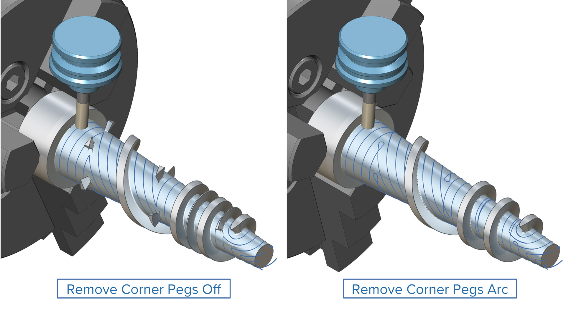
Remove Corner Pegs
Challenge: In offset roughing patterns, passes may be skipped in narrow regions or corners, leaving behind material that could lead to tool collisions or incomplete roughing.
Solution: The system now identifies these critical regions and inserts additional toolpath passes before proceeding to the next depth level, ensuring complete material removal.
Benefits: This feature improves machining safety by preventing tool collisions and ensures that all intended material is removed during roughing, resulting in a cleaner and more reliable process.
Multi-Axis Roughing |
Area Roughing
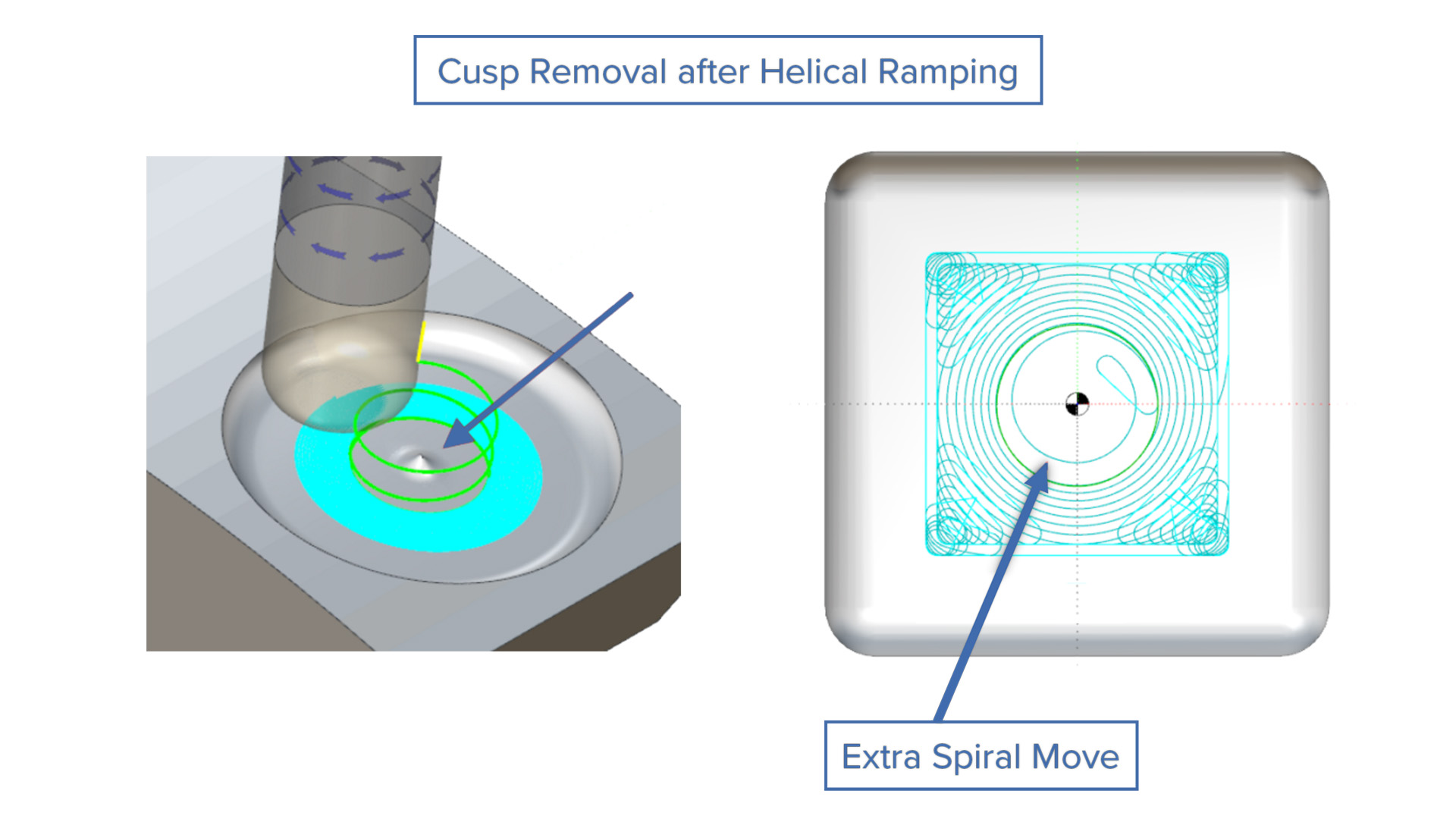
Cusp Removal after Helical Ramping
Challenge: After helical ramping, cusps were visible due to the wide helix diameter of bullnose mill tools.
Solution: This feature creates an extra pass over the center of the helix to remove the cusp.
Benefits: This new feature allows the use of larger bullnose tools for ramping operations, enabling wider helix diameters for more productive ramping.
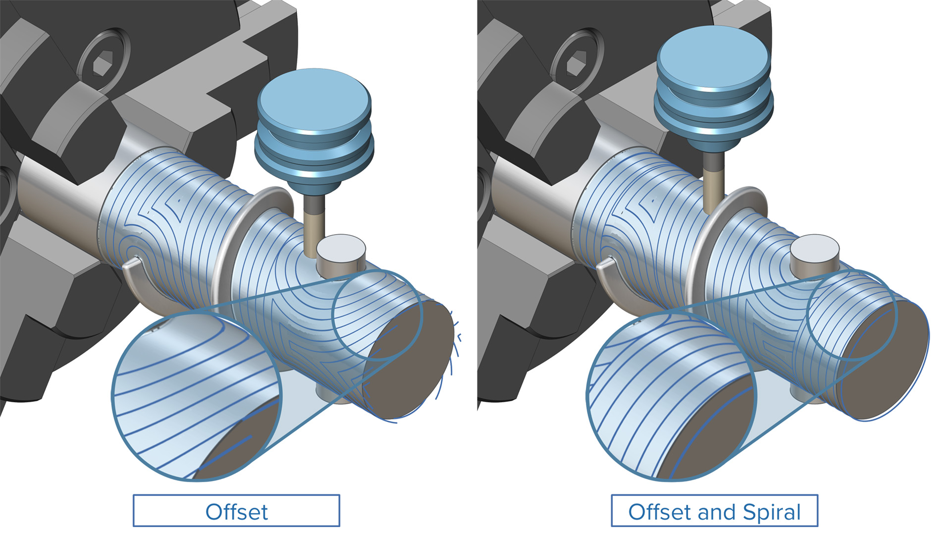
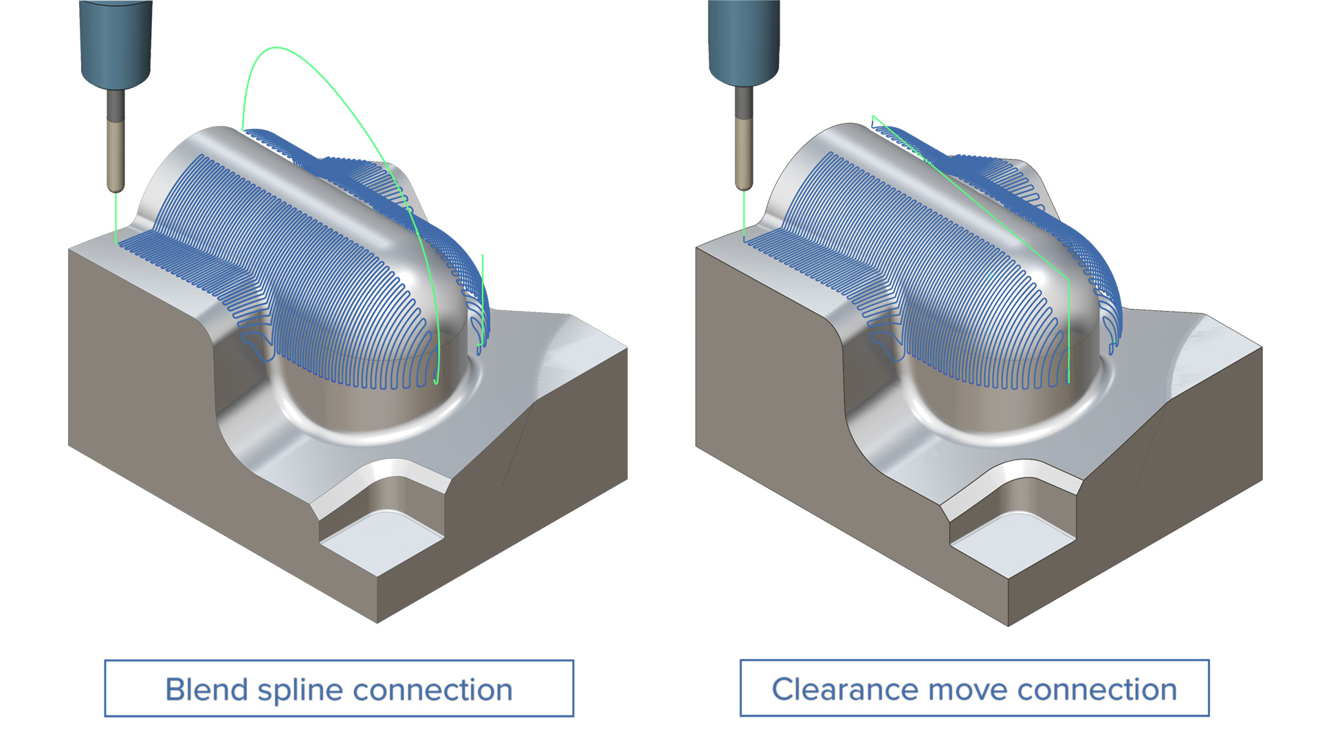
Challenge: Traditional offset cuts on long surfaces can leave visible marks at the joins, reducing the overall surface quality and smoothness.
Solution: The new method intelligently combines offset and spiral slicing, using spiral cuts only when safe to do so, ensuring continuous tool engagement and minimizing transitions.
Benefits: This enhancement improves the surface finish, reduces the number of linking moves, and enhances consistency across the entire machined surface.
Multi-Axis Surface Finishing | Geodesic Machining
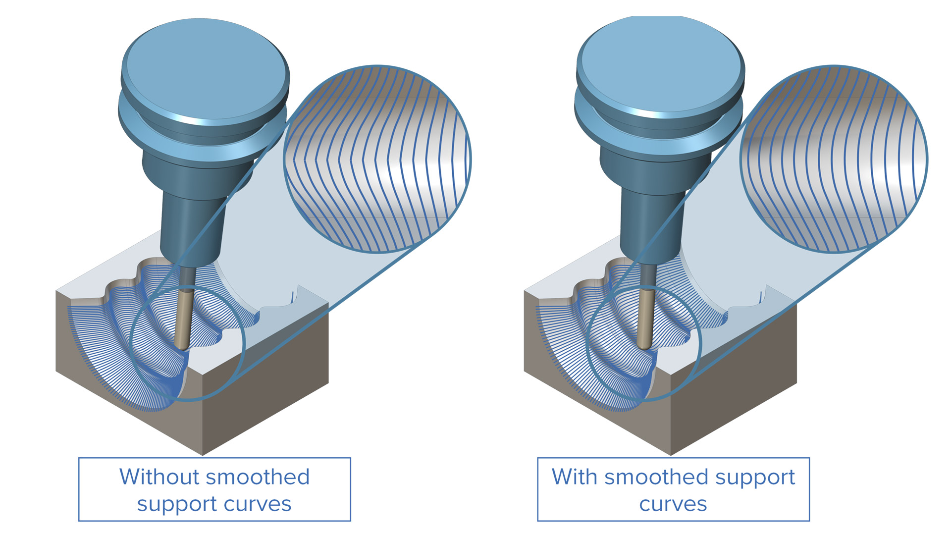
Enhanced Morph Pattern for Geodesic Machining
Challenge: The current design of the morph pattern can create kinks or abrupt changes in the toolpath when applied to certain geometries.
Solution: This new feature iteratively generates smoothed support curves between morph curves prior to pattern generation. As a result, the final morph pattern is smoother than ever before.
Benefits: With the introduction of this feature, users can achieve improved surface quality and reduced machining time.
Multi-Axis Surface Finishing | Wall, Floor and Rest Finishing
Bull Nose Tool Support for Wall Finishing
Challenge: Bull nose tools are commonly used in roughing, but there was no direct way to use them in semi-finishing wall operations. This made it harder to prepare surfaces for high-precision tools, such as barrel cutters.
Solution: Bull nose tools can be used in wall finishing operations, making it easier to perform final finishing.
Benefits: This feature improves surface finish, reduces tool changes and enhances overall efficiency.
3-Axis Finishing |
Mesh Finishing
Links Between Regions Extended Support
Challenge: Previously, this feature was limited to Constant Z patterns and did not include other finishing cycles.
Solution: An additional linking option for regions has been added for all finishing cycles other than Project curves, including Constant Z 3-Axis Undercut machining, providing more refined control over the linking behavior.
Benefits: With this feature, users can easily handle complex linking scenarios without compromising on efficiency.
3-Axis Finishing | Mesh Finishing
Corner Peg Removal for Constant Z + Constant Cusp
Challenge: Offset-type toolpath patterns like Constant Cusp often generate unwanted cusps in corner regions— especially where the pattern collapses or where corner smoothing shifts the toolpath. These cusps disrupt the surface finish and typically require time-consuming manual polishing to remove.
Solution: Additional peg loops are now incorporated in corner areas. This adjustment is implemented to maintain uniform toolpath patterns during machining, specifically targeting corners.
Benefits: With the introduction of this feature, consistent surface quality is achieved, and manual labor is reduced.
3-Axis Finishing |
Mesh Finishing
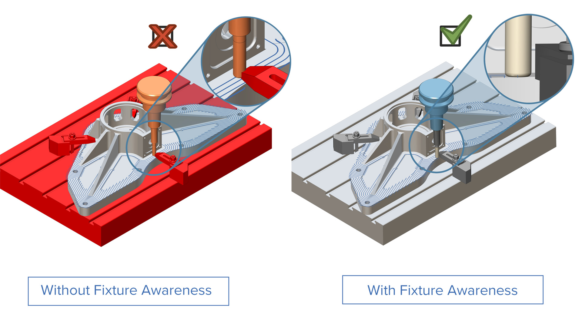
Fixture Awareness for Flatland Machining
Challenge: When fixtures cannot be defined during the toolpath calculation, the CAM system cannot automatically trim the toolpath to avoid collisions. As a result, users must manually create containment boundaries to prevent the tool from gouging fixtures. The absence of fixture definition means the software lacks awareness of obstacles, so it cannot automatically adjust toolpaths for collision avoidance.
Solution: Fixtures can now be defined using surfaces. The toolpath calculation automatically recognizes these surfaces and trims the toolpath to avoid collisions and maintain clearance from the fixtures.
Benefits: This feature eliminates unnecessary manual programming and extensive containment creation, resulting in increased ease of use, reduced programming time, and the generation of safer toolpaths.
3-Axis Finishing |
Mesh Finishing
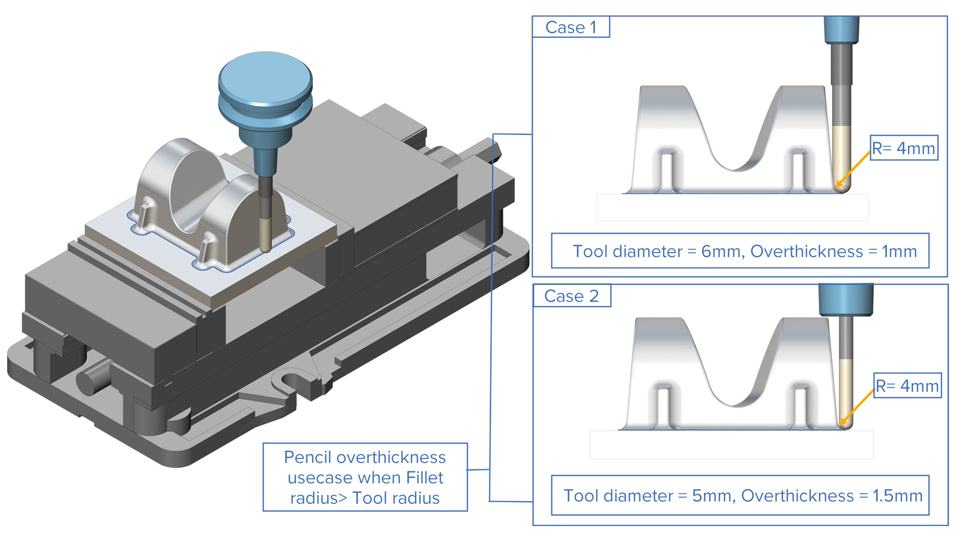
Overthickness Option for Pencil Machining
Challenge: On parts with slightly varying fillets—often caused by construction or tessellation inaccuracies—corner detection algorithms may fail to recognize some fillets if the tool is too small to properly identify them. This results in undesired toolpath fragmentation or even completely missed machining of certain areas.
Solution: A virtual overthickness is added to the tool, and corner detection is performed using this oversized tool model. This approach enables the detection of more fillets and prevents toolpath fragmentation.
Benefits: With this new feature, fillets are detected and machined more consistently, tool changes are minimized, and overall machining time is reduced.
3-Axis Roughing | Offset/Parallel Roughing
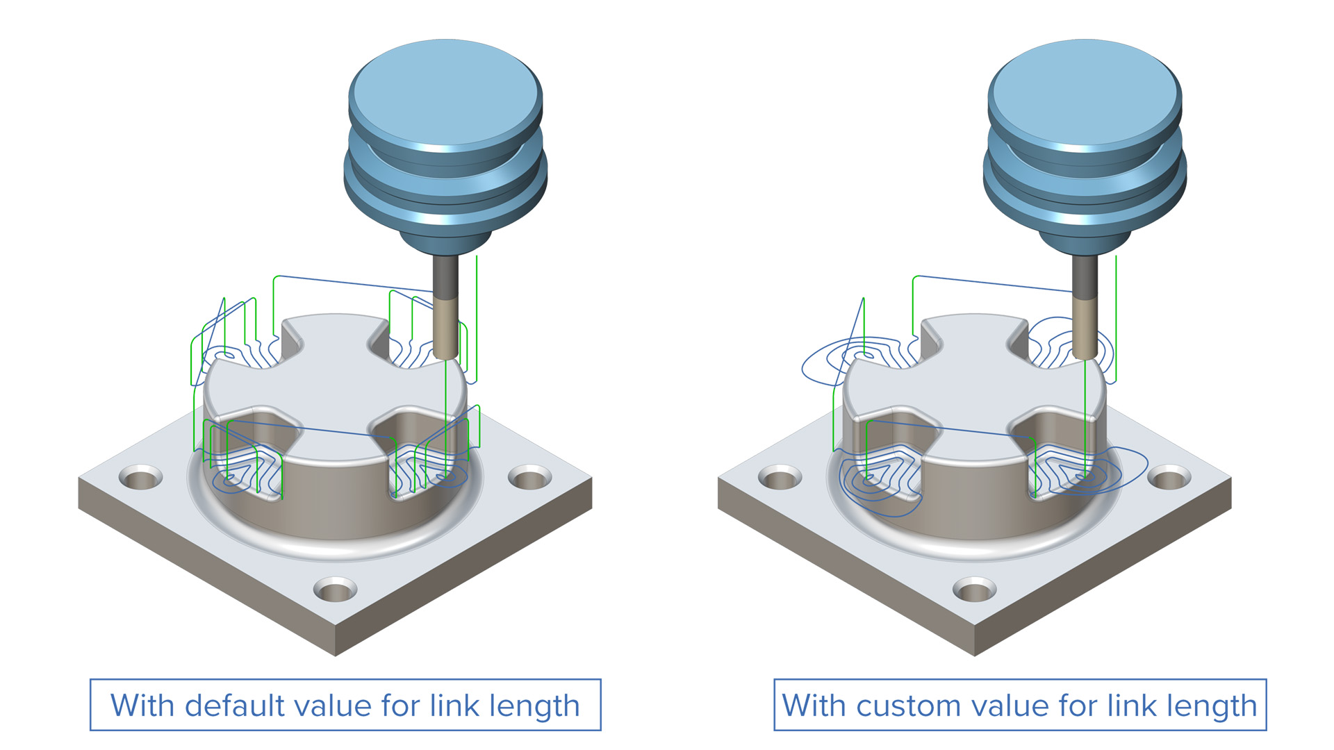
Within Group Size for Offset Roughing
Challenge: The current hardcoded limitation—restricting within-group link distances to 2× the tool diameter—forces unnecessary tool retracts during machining. This leads to inefficient tool movement and increased cycle times.
Solution: A new “Within Group Size” parameter specifies the maximum allowable distance between the start and end points of adjacent roughing toolpath cuts.
Benefits: This new feature allows users to customize the conditions for creating direct and blend spline links, keeping the tool at the slice level whenever possible. This provides greater machining flexibility and eliminates undesired tool retracts.
3-Axis Roughing | Offset/Parallel Roughing
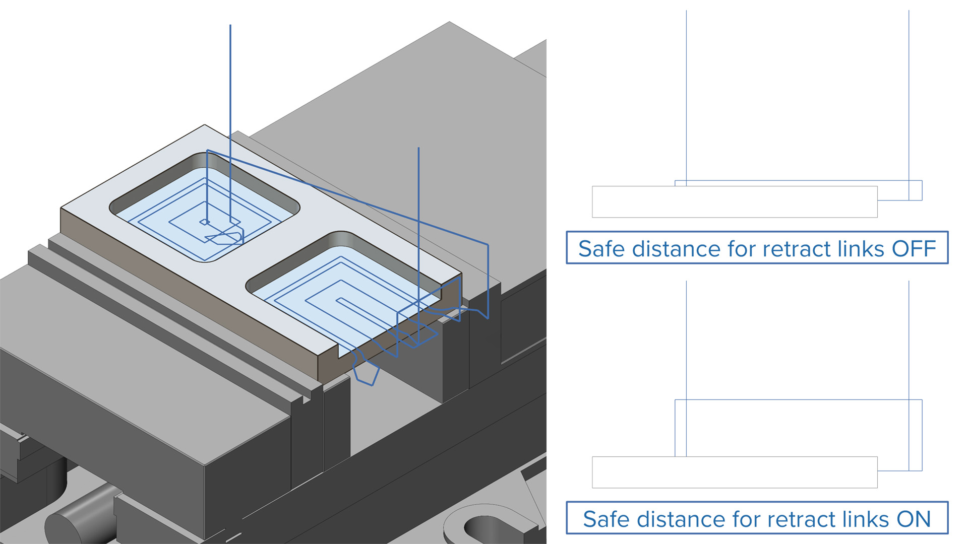
Enhanced Air Move Safety Distance
Challenge: Previously, the minimum clearance between retract links and in-process stock was limited to the cutting tolerance, which could result in insufficient space for chip evacuation and increase the risk of tool breakage.
Solution: This improvement allows users to define a custom air move safety distance, even when optimization is enabled, ensuring adequate clearance from the stock during retract moves.
Benefits: This enhancement provides safer toolpath linking, reduces the risk of collisions, and helps optimize machining time by maintaining efficient and secure retract heights.
3-Axis Roughing |
Adaptive Roughing
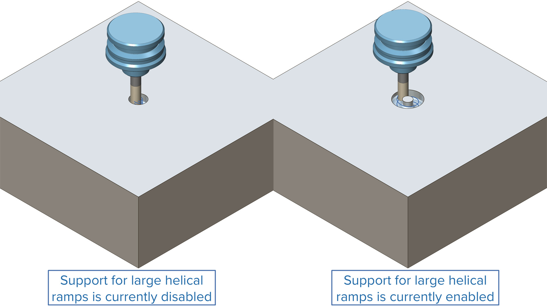
Large Diameter Helical Ramp Support
Challenge: Previously, ramp diameters were restricted to 95% of the tool diameter, limiting the ability to optimize tool entry conditions in materials that allow for more aggressive ramping.
Solution: The diameter limitation has been removed, and the system now supports proper processing of stock pillars formed during large helical ramping.
Benefits: Users can now tailor ramping strategies to suit specific material properties, improving tool engagement, reducing wear, and enhancing overall machining flexibility.
Turning
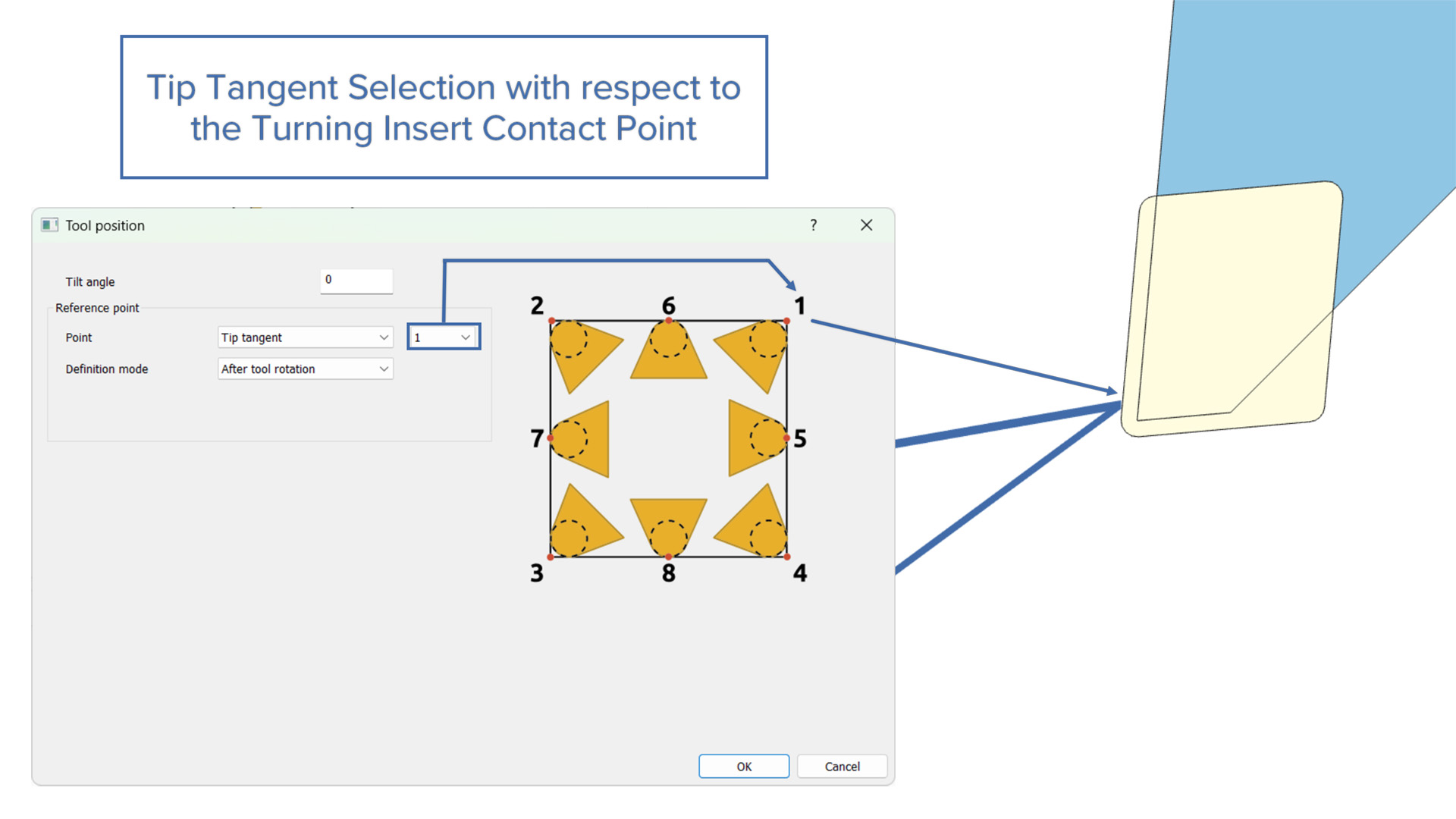
Tip Tangent Selection with Respect to the Turning Insert Contact Point
Challenge: During turning operations, the turning tool insert is zeroed with the tool contact point. This leads to multiple tip tangent positions in a toolpath.
Solution: This new feature allows users to select the tip tangent with respect to the turning insert contact point.
Benefits: With this feature, user achieve higher accuracy and a better-quality surface finish for the given geometry/part.
Turning
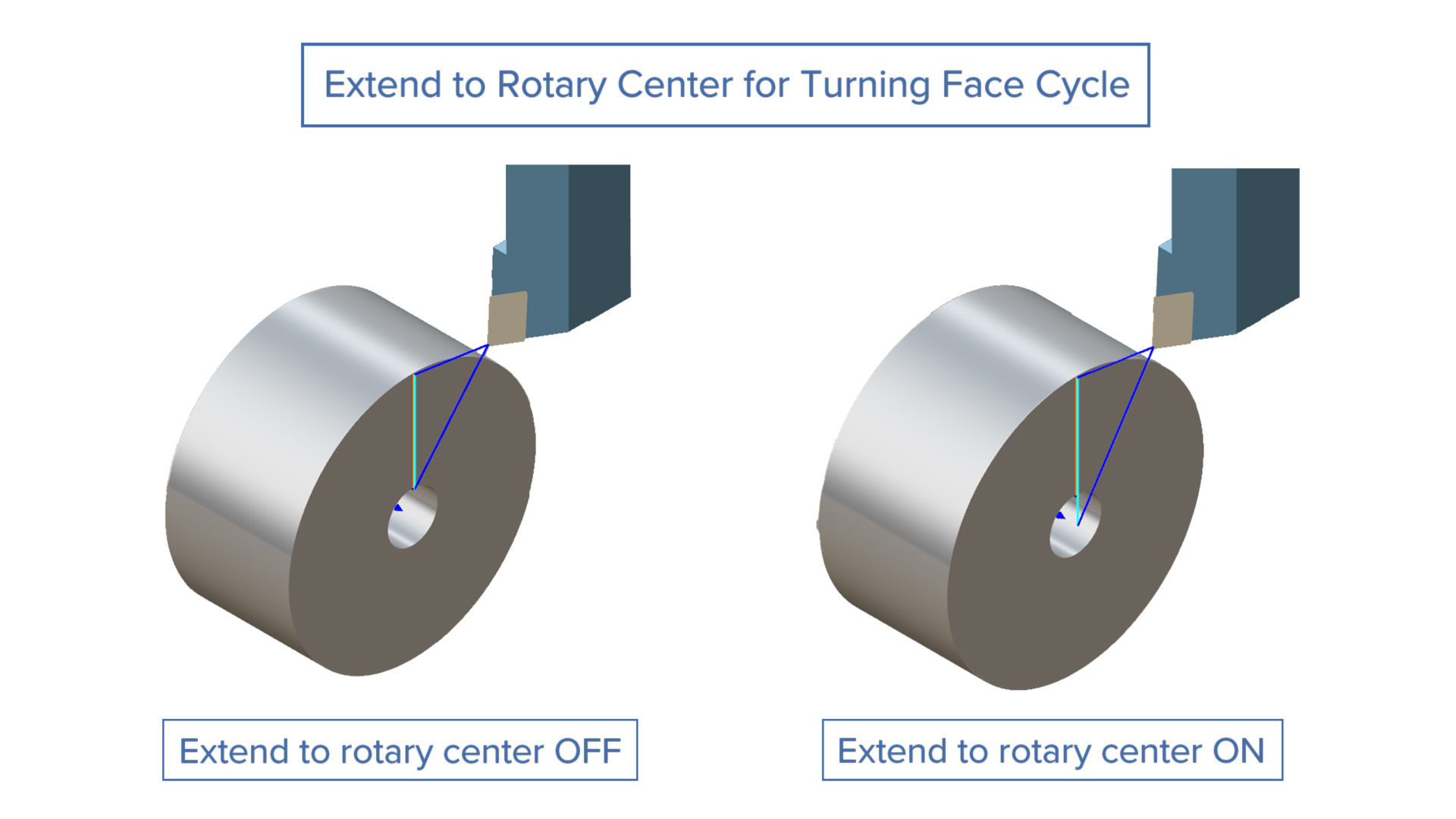
Extend to Rotary Center for Turning Face Cycle
Challenge: During toolpath creation for a hollow part, users were unable to generate face cycles for the drive curve. The toolpath would extend to the rotary center, which increased the cycle time.
Solution: Users can now unselect the “Extend to Rotary Center” option to prevent the creation of extended toolpaths.
Benefits: This option generates an optimized face toolpath that reduces the cycle time.
Turning
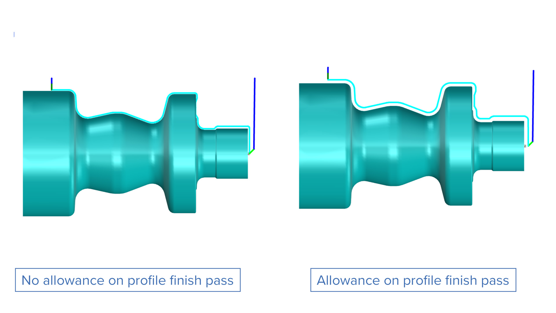
Fishing Allowance for B-Axis Profile Turning
Challenge: When preparing a component for subsequent non-machining processes like grinding, the user must set an appropriate finishing allowance during the machining operation. The challenge is to leave just enough extra material: too much increases machining time and costs, while too little risks insufficient stock for grinding, leading to poor surface finish or dimensional inaccuracies.
Solution: An offset parameter has been introduced for defining individual allowance settings in the radial direction, the axial direction, or globally across all geometries.
Benefits: This feature takes additional material into consideration during finishing for operations such as grinding, honing, or polishing, ensuring precise dimensions and surface quality. It also provides greater process flexibility to accommodate variations in machining conditions, tool wear, and material properties, enhancing production reliability.
Simulation
Simulation SDK |
CNC Simulation
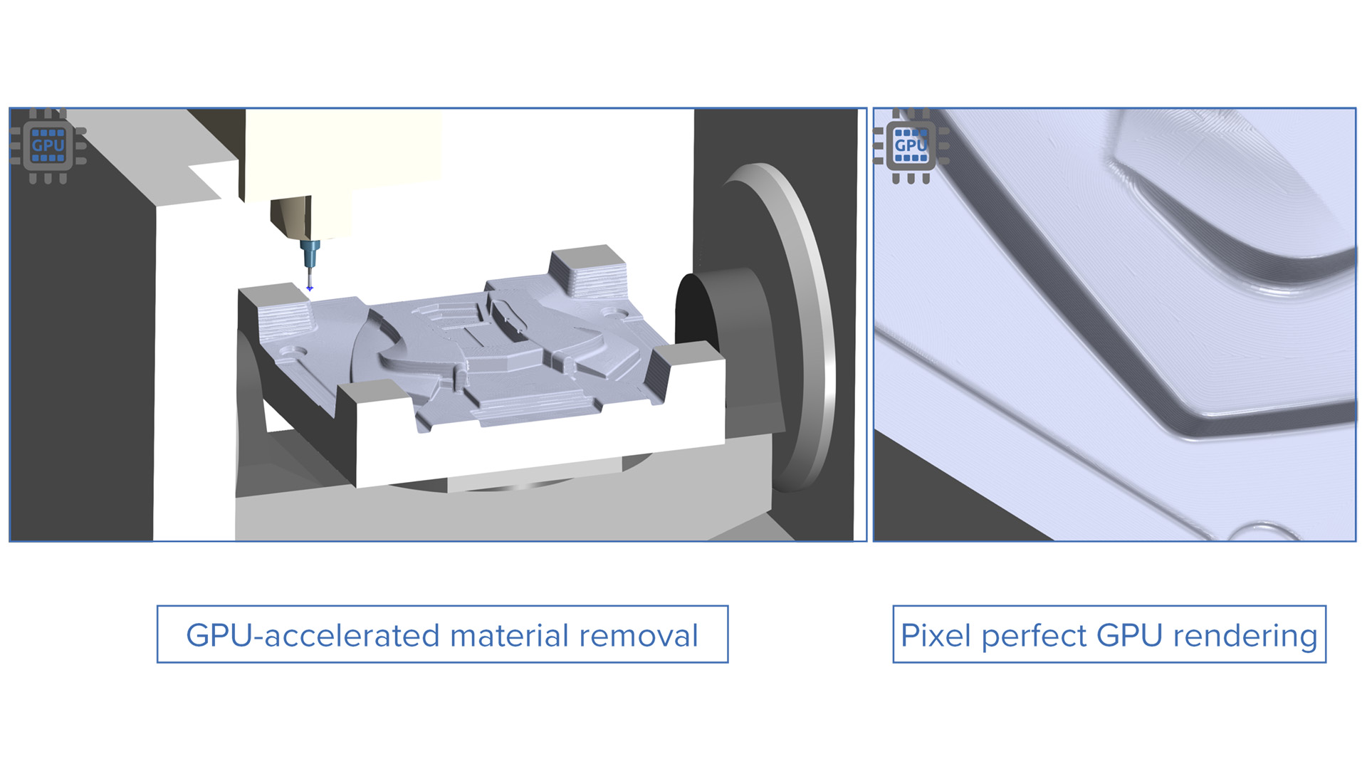
Support for Gpu-Accelerated Material Removal Simulation and Collision Checking
Challenge: Simulating material removal while checking for potential tool collisions with the in-process stock is computationally intensive, leading to slowdowns in complex machining simulations.
Solution: Leverage GPU acceleration to optimize both material removal and collision checking.
Benefits: Increased simulation speed, particularly for large-scale machining operations, while maintaining precise collision detection.
Simulation SDK |
CNC Simulation
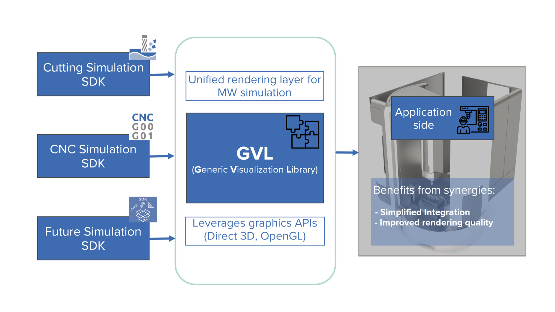
Generic Visualization Library
Challenge: Integrating workpiece and machine simulations separately with a Simulation SDK involves managing two distinct visualizations, increasing complexity and preventing shared benefits like unified collision checks and streamlined workflows.
Solution: A Generic Visualization Library has been developed for use across any displayable module within the Simulation SDK. It enables seamless integration with modern Graphics APIs and supports the latest visualization features.
Benefits: This new feature simplifies side-by-side integration of workpiece and machine simulations. Graphics throughput and performance are also improved.
Simulation SDK |
Cutting Simulation
Gradient-Based Deviation Mode for Pixel-Perfect GPU Rendering
Challenge: Fixed color bands can mask subtle variations in gouges or excess material, making it difficult to detect fine surface deviations during inspection.
Solution: This enhancement introduces gradient shading to the deviation analysis, allowing users to perceive nuanced differences that were previously hidden between threshold bands.
Benefits: Improved visual clarity helps users detect and interpret subtle gouges or excess material more easily during inspection.
Simulation Systems | NC Editor
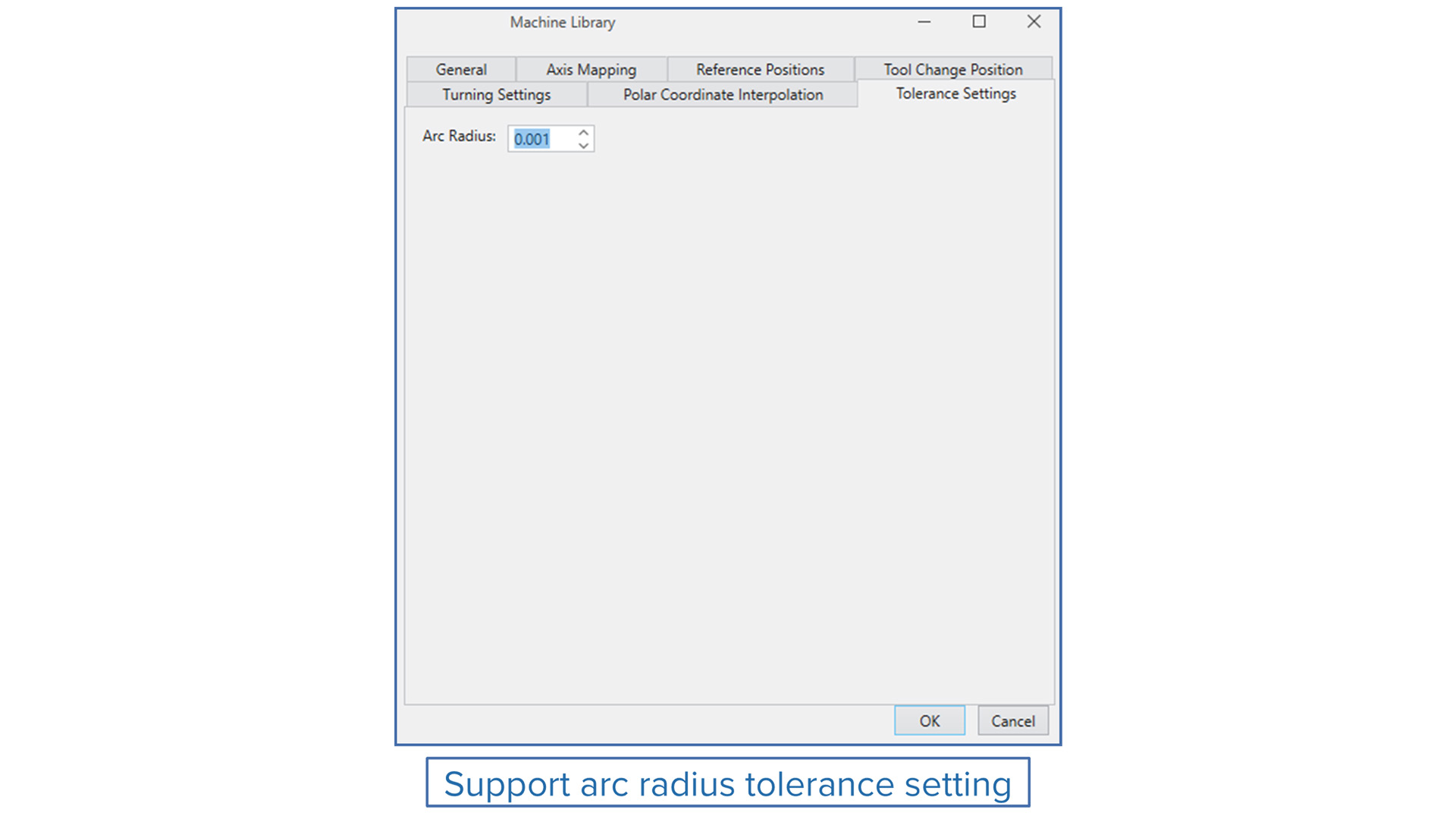
Arc Radius Tolerance Setting
Challenge: Previously, if the start and end points of an arc were not within the default tolerance, NC Editor failed to compute the arc center, resulting in simulation errors.
Solution: A new setting enables users to specify the arc tolerance, allowing the system to account for minor discrepancies and accurately determine the arc center.
Benefits: This enhancement ensures smooth and error-free simulation of arc G-code, increasing reliability and reducing manual troubleshooting.
Simulation Systems |
Machine Simulation
Possibility of Stacking of Multiple Mounting Heads for Machine Simulation
Challenge: Managing multiple magazine heads is cumbersome and inefficient, particularly when adapting to varying mounting requirements. This complexity leads to increased setup time, higher risk of errors and reduced operational flexibility.
Solution: This new feature allows one magazine head to be mounted onto another by defining mount adapters within the magazine heads. This configuration enables the creation of hierarchical magazine assemblies.
Benefits: This new feature reduces setup times and streamlines operations via easy-to-configure magazine heads. Customizable mount adapters provide flexibility for various mounting requirements, while an intuitive design minimizes errors and ensures precise configurations.