The 2026.04 release makes turning, roughing, and verification easier and safer. It gives you finer control over depths, boundaries, and stock allowances, plus smarter High Dynamic Turning options to protect tools and improve surface quality. At the same time, faster, more detailed simulation and streamlined post/file handling help you check jobs quickly and keep NC output compatible with real machines.
Toolpath
Multi-Axis Roughing |
Automatic 3+2-Axis Roughing
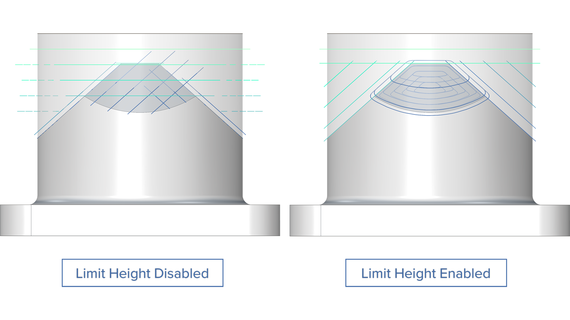
Limit Height for Manual Directions
Challenge: The manual 3+2 automatic roughing mode is widely used to achieve the desired level of processing. Because depth control could not be applied independently to each machining direction, multiple separate operations were necessary to achieve the target result.
Solution: This new feature provides depth control for the user-defined machining directions.
Benefits: With the added depth control, users can now achieve the desired level of machining in a single operation, reducing overall programming and machining time and making 3+2 automatic roughing more flexible. The height limit adjustments also eliminate the creation of extra toolpath artifacts, further reducing the machining time.
Multi-Axis Roughing |
Automatic 3+2-Axis Roughing
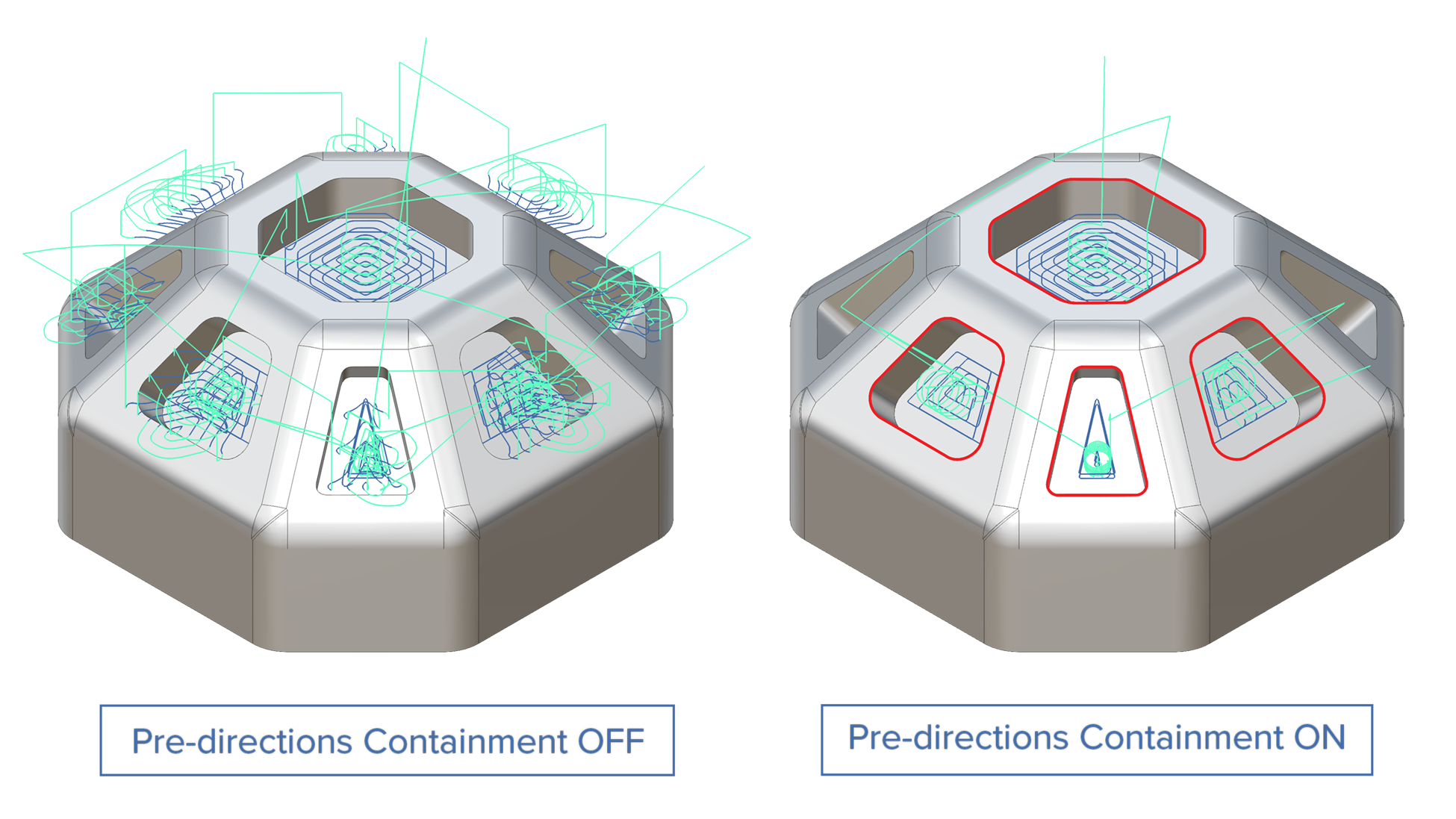
Pre-Axis Trimming Boundary for Manual Directions
Challenge: The inability to define machining boundaries during a 3+2 manual roughing operation generates unnecessary toolpath segments, substantially increasing production costs and reducing tool life.
Solution: Direction-specific 2D containment boundaries let you define separate machining limits for each axis. Set unique boundaries per direction to control material removal precisely where needed, preventing toolpath segments from extending beyond the intended machining area.
Benefits: Eliminate unnecessary toolpath segments and reduce machining time by preventing over-machining. Extend tool life by removing only the material needed in each direction, reducing wear from redundant cutting passes.
Multi-Axis Finishing | Rotary Machining Finishing
Collision Avoidance Surfaces
Challenge: Protecting critical areas during machining can be challenging without precise control over toolpath. This results in surface damage, reduced quality or unsafe operation.
Solution: Users can designate one or more avoidance surfaces with custom clearance offsets, ensuring toolpaths automatically navigate around sensitive regions during rotary operations.
Benefits: This enhancement prevents toolpath collisions with critical surfaces, eliminating the risk of part damage and reducing costly rework through automated collision avoidance.
3-Axis Finishing |
Corner Finishing
Max. and Min. Engagement Control for Corner Finishing
Challenge: During Corner Finishing operations, uncontrolled cutter engagement in deep slots can result in over engagement, risking tool breakage and damage to the part. Additionally, areas with minimal rest material can generate inefficient toolpath fragments with no meaningful material to remove.
Solution: Set maximum engagement thresholds that prevent the toolpath from entering deep slots where engagement would exceed safe limits. Simultaneously, define minimum engagement thresholds to exclude toolpath segments where remaining material is too small for effective cutting.
Benefits: With this feature users can:
Eliminate the risk of tool breakage in Corner Finishing operations by ensuring engagement levels stay within safe limits throughout the calculated toolpath.
Achieve more consistent surface quality by avoiding over-aggressive engagement and inefficient micro-passes.
Reduce cycle time by excluding unnecessary toolpath segments with minimal material engagement.
3-Axis Finishing |
Corner Finishing
Spiral Pattern for Corner Finishing
Challenge: Using linking passes for corner finishing forces a change in direction which compromises surface quality in the corners.
Solution: With this new feature, users can deploy continuous spiraling instead of linking passes, thereby achieving better surface quality on corners.
Benefits: This feature enables users to achieve better surface quality in the corner regions by maintaining a continuous tool engagement and machining speed.
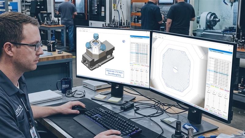
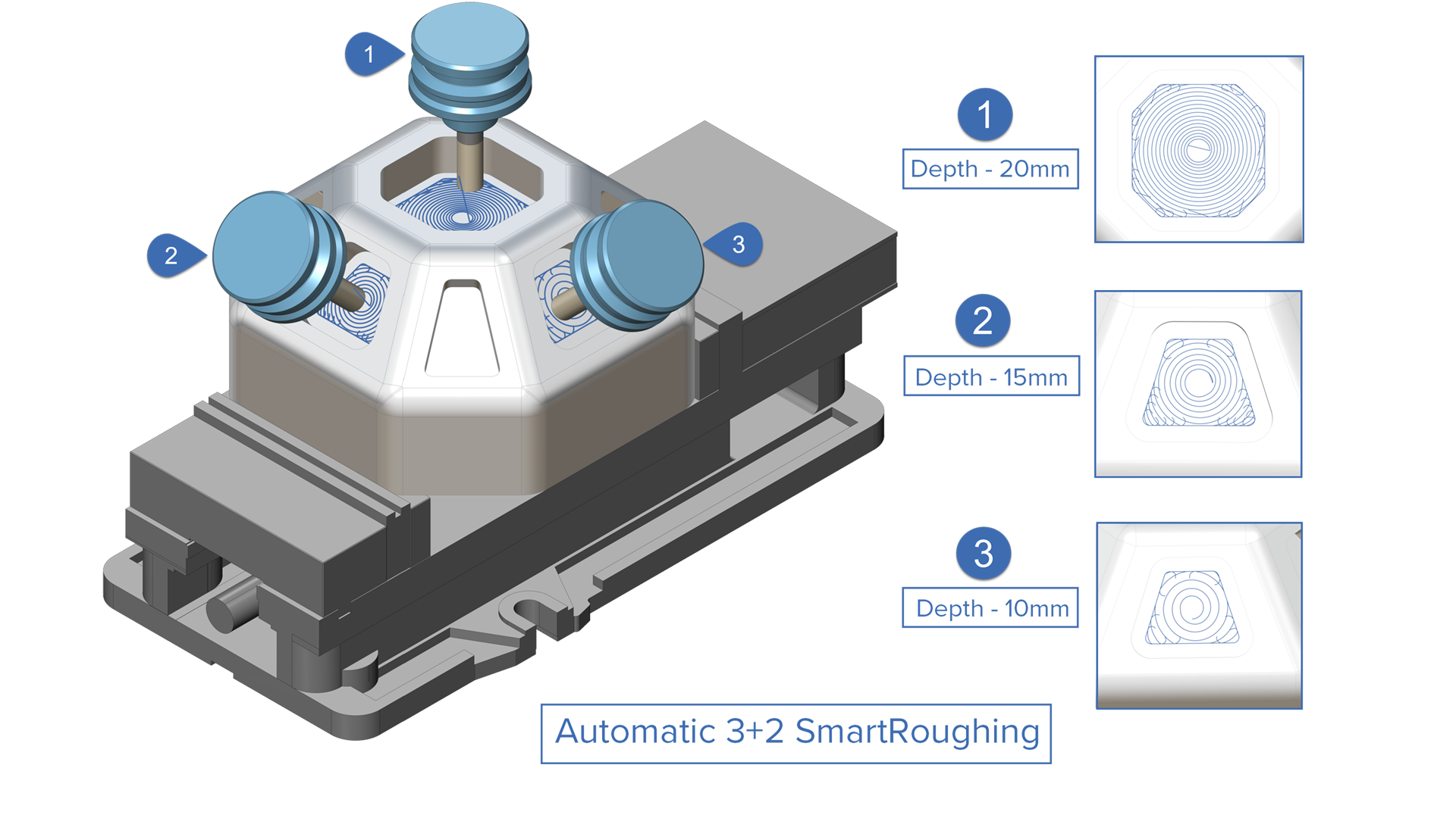
3-Axis Roughing | SmartRoughing
Automatic 3+2 SmartRoughing
Challenge: Conventional 3+2 roughing strategies provide good access to the part, but use fixed and often conservative cutting parameters. Users rely on experience and guesswork to manually choose feeds, speeds and stepovers, which increases programming time and limits productivity.
Solution: SmartRoughing 3+2 brings physics-based optimization to multi-axis roughing, removing the guesswork and combining the best of two worlds:
Automatic 3+2 automatically determines optimum machine tool axis orientations to fully rough a part.
SmartRoughing automatically calculates optimum cutting parameters for safe and efficient material removal.
Benefits: SmartRoughing 3+2 replaces guesswork with scientific precision to reduce the amount of trial error and deliver clear performance gains for programming, machining and overall shop efficiency.
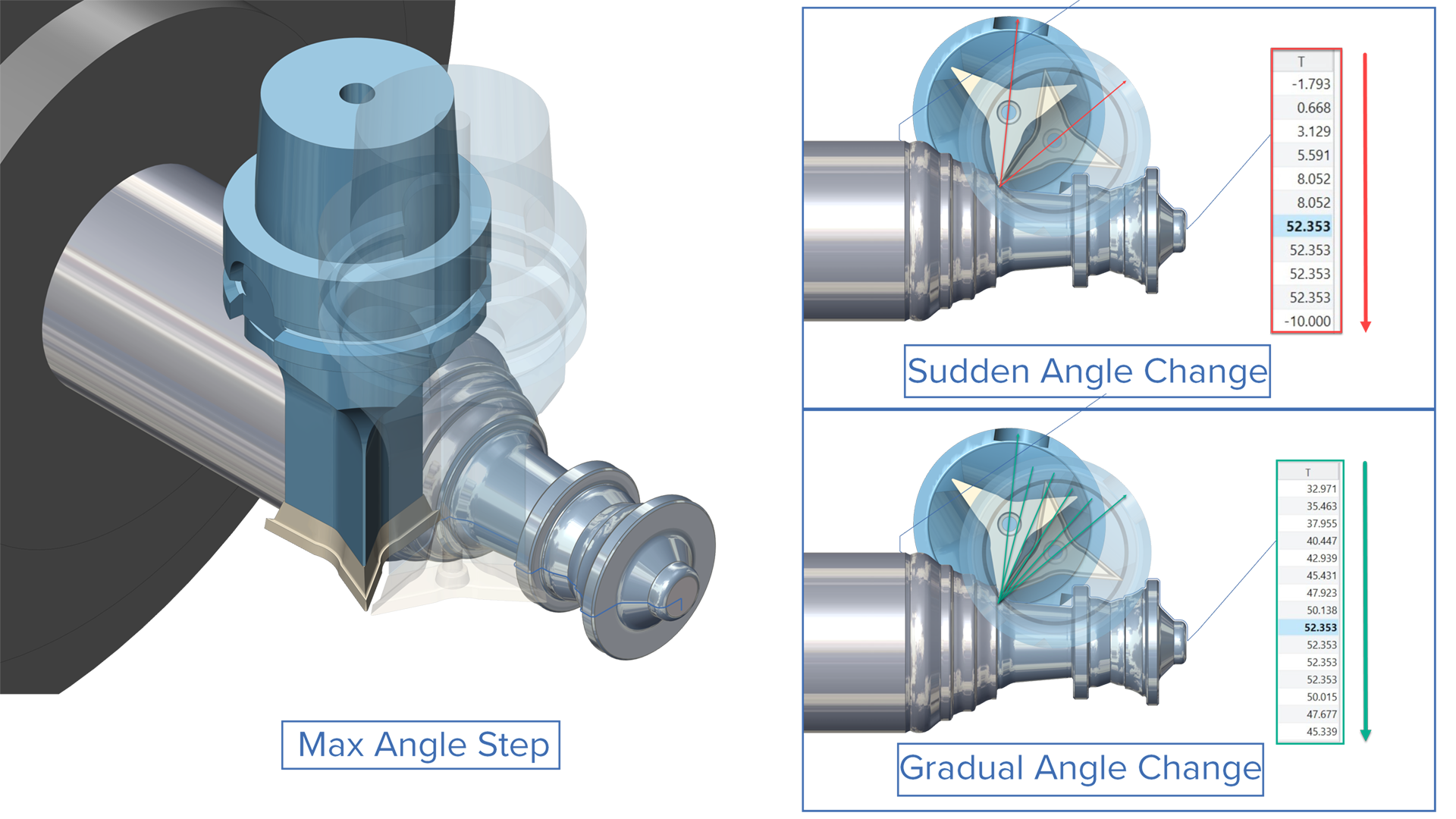
Turning | High Dynamic Turning
Maximum Angle Step Control for Dynamic Toolpaths
Challenge: Being able to limit the angle change between two consecutive toolpath points is important for avoiding large and sudden changes in tool orientation, which could otherwise cause overcutting or even collisions.
Solution: With the new “Max Angle Step”, it is possible to limit the tool orientation change between consecutive toolpath points. If the required rotation is too large, intermediate points are automatically added to split the motion into smaller angle steps, ensuring predictable and safer tool movement.
Benefits: This new feature ensures predictable tool motion with controlled orientation changes, reducing unexpected machine behavior and collision risks. It also improves machining accuracy through smoother tool engagement, minimizing overcutting errors and maintaining consistent surface quality.
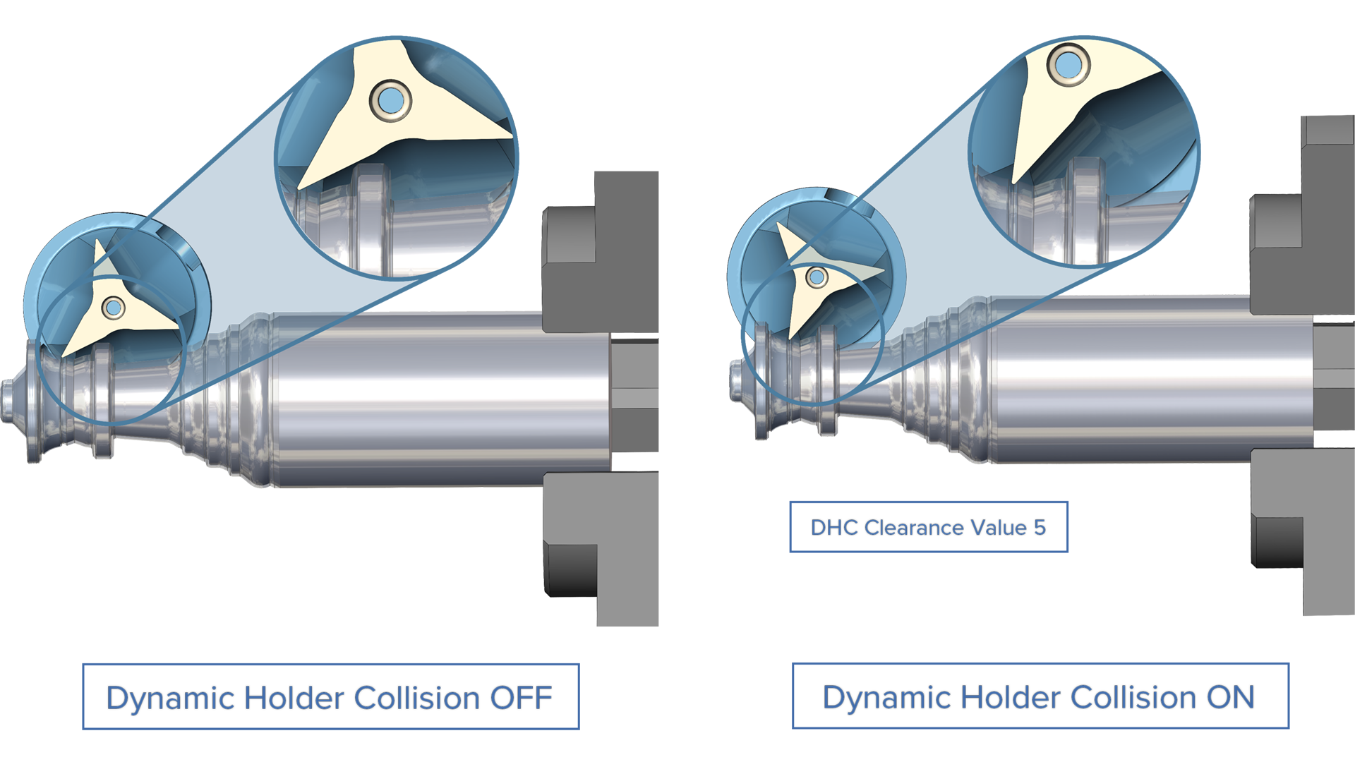
Turning | High Dynamic Turning
Dynamic Holder Collision Prevention for High Dynamic Turning
Challenge: When using wide rotation angles in high dynamic turning, the insert’s non-cutting edges can rub against the part contour, causing tool damage, surface defects, and scrapped parts.
Solution: The Dynamic Holder Collision Prevention parameter automatically monitors the gap between the insert’s non-cutting edges and the part surface, maintaining a user-defined safety clearance throughout the toolpath.
Benefits: With this new parameter users can:
Eliminate insert rubbing and tool damage during high dynamic turning operations.
Reduce part scrapping caused by unwanted contact.
Be more confident about using aggressive rotation angles.
Turning | High Dynamic Turning
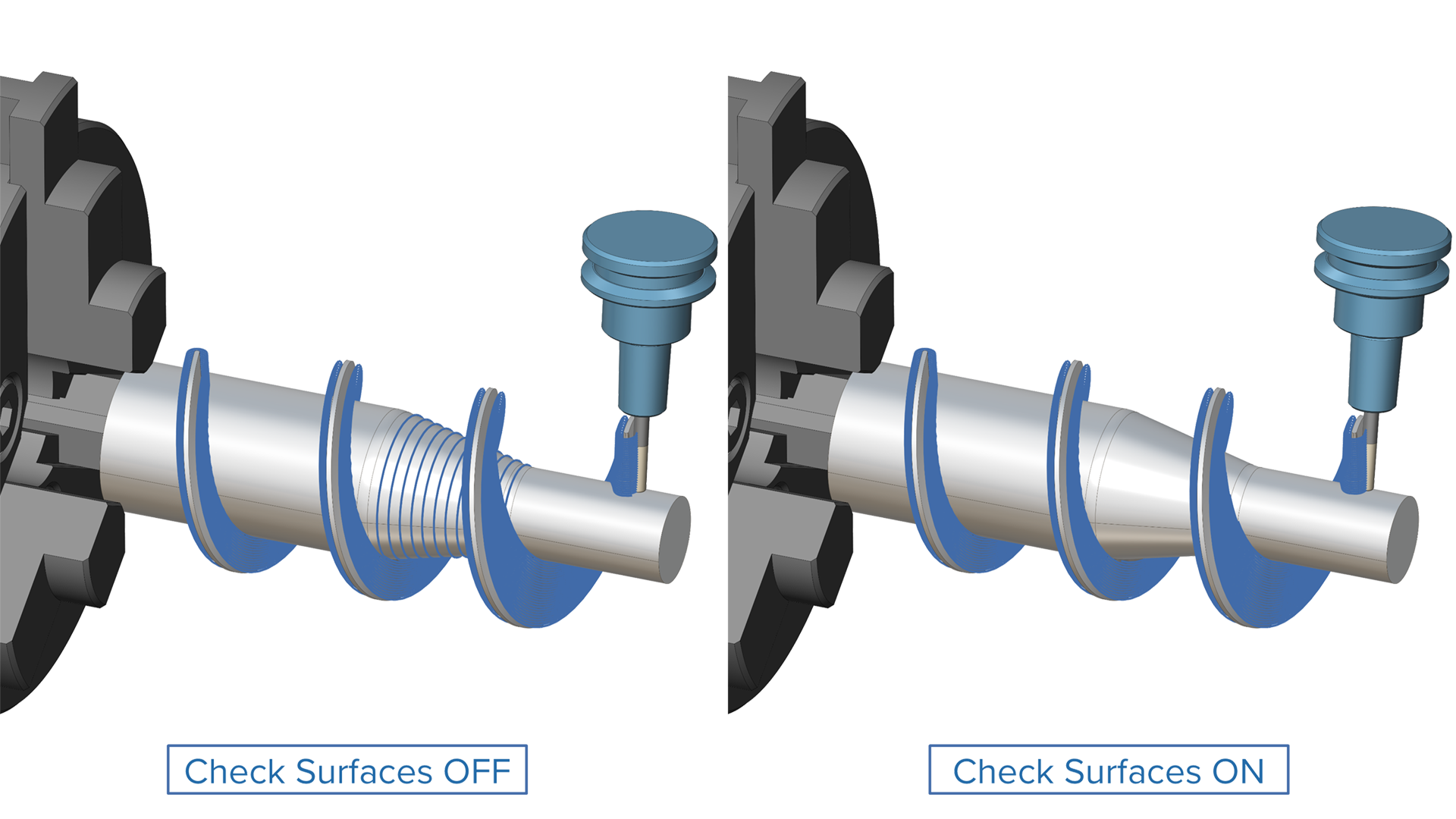
Follow Tool Angle Clearance for Static Rough Cycle
Challenge: When machining with Follow Tool Angle, the backside of the turning tool can unintentionally rub against the in‑process stock. This increases the risk of unwanted marks, heat generation and potential tool or surface damage.
Solution: A new safety angle clearance can now be applied to HDT Static Rough toolpaths that follow the tool angle. This allows users to define a controlled angular gap between the tool and the in‑process stock, preventing unwanted tool‑to‑material contact.
Benefits: This enhancement creates safer and more reliable roughing toolpaths that avoid areas where the backside of the tool might otherwise gouge or rub in‑process stock. This leads to smoother machining, reduced risk of damage and a more controlled cutting process.
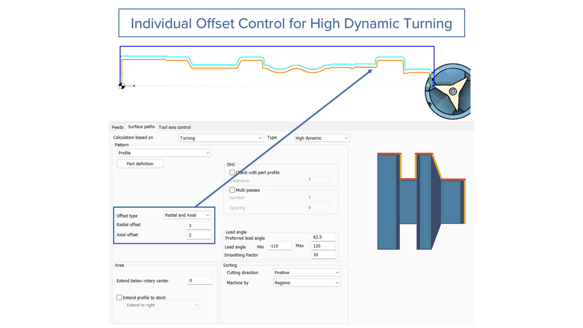
Turning |
High Dynamic Turning
Individual Offset Control for High Dynamic Turning
Challenge: When preparing a component for a subsequent non-machining process, e.g. grinding, it is important to set an appropriate finishing allowance that leaves just the right mount of extra material.
Solution: With the new Offset parameter users can set allowances radially, axially, or globally (uniform across all surfaces). This optimizes material removal based on how each surface is processed in subsequent operations.
Benefits: Leave precisely the right amount of material for subsequent grinding, honing, or polishing operations – enough for dimensional accuracy and surface quality, but not so much that you waste machining time. Accommodate varying conditions like tool wear and material properties without over-provisioning allowances across all directions.
Turning |
Turning Advanced
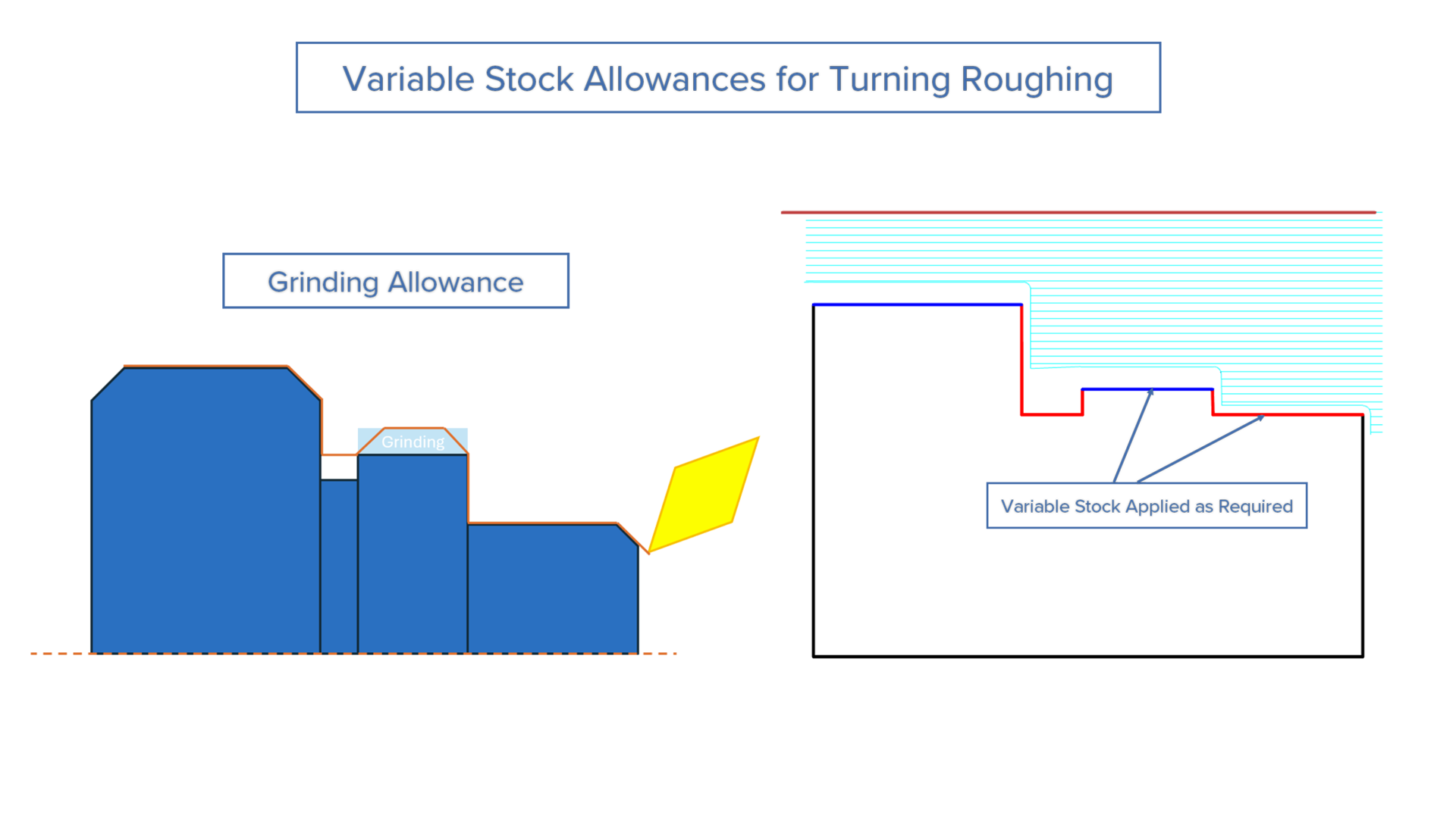
Variable Stock Allowances for Turning Roughing
Challenge: Users cannot apply variable stock allowances during roughing operations in turning, forcing them to use uniform material removal across the entire part contour. This prevents optimizing material distribution for subsequent finishing or non-cutting operations like grinding.
Solution: Segment-based stock control allows users to assign individual stock allowance values to each segment of the drive curve during roughing cycles, matching the flexibility already available in finishing operations.
Benefits: This optimizes machining time by leaving excess material only where needed for finishing or grinding. Overall cycle time is reduced while maintaining part accuracy by controlling material distribution throughout the machining process.
Turning |
Turning Basic
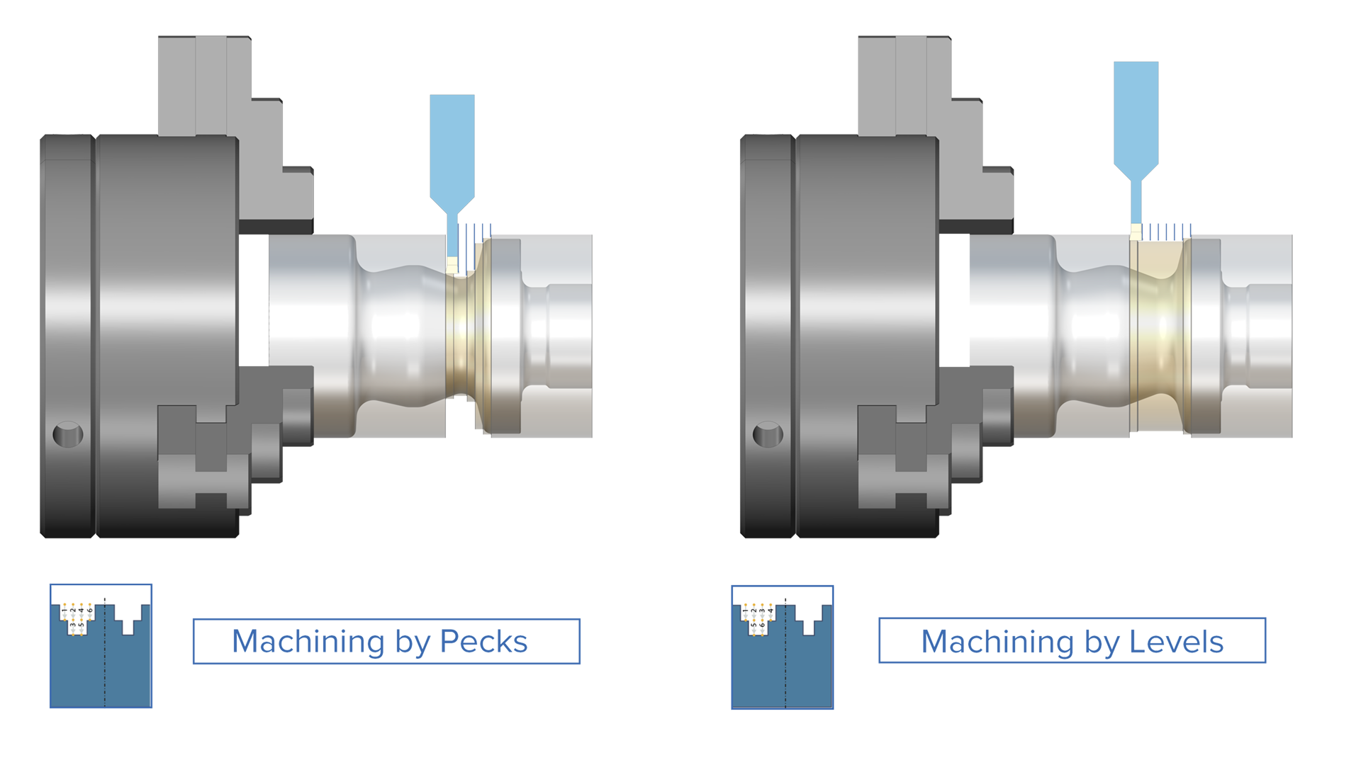
Multi-Level Peck Grooving Cycle
Challenge: Using pecking in deep grooves without a depth step on hard materials can cause vibrations and high tool loads, leading to unstable cutting, reduced tool life and possible surface quality problems.
Solution: The new “Levels” option divides each peck cycle into smaller, incremental depth steps, distributing cutting forces progressively throughout the groove depth.
Benefits: Machining deep grooves with the “Levels” option delivers: reduced vibration, improved chip evacuation, lower tool load, longer tool life, and a significantly reduced risk of tool breakage.
Turning | Turning Basic
Sharp Corner Support for Turning Rough Cycle
Challenge: When roughing components with sharp external corners, the toolpath automatically rolled over the edges, blending them. This forced users to accept rounded corners even when sharp edges were required for the design specification.
Solution: This new feature gives users the option to generate a toolpath with either corner rollover or sharp corners.
Benefits: With the introduction of this feature, sharp corners can be produced on turned parts in line with design requirements, without the need for manual post-processing. It also helps reduce tool wear and prevents surface hardening by removing unnecessary edge blending passes.
Simulation
Simulation SDK |
CNC Simulation
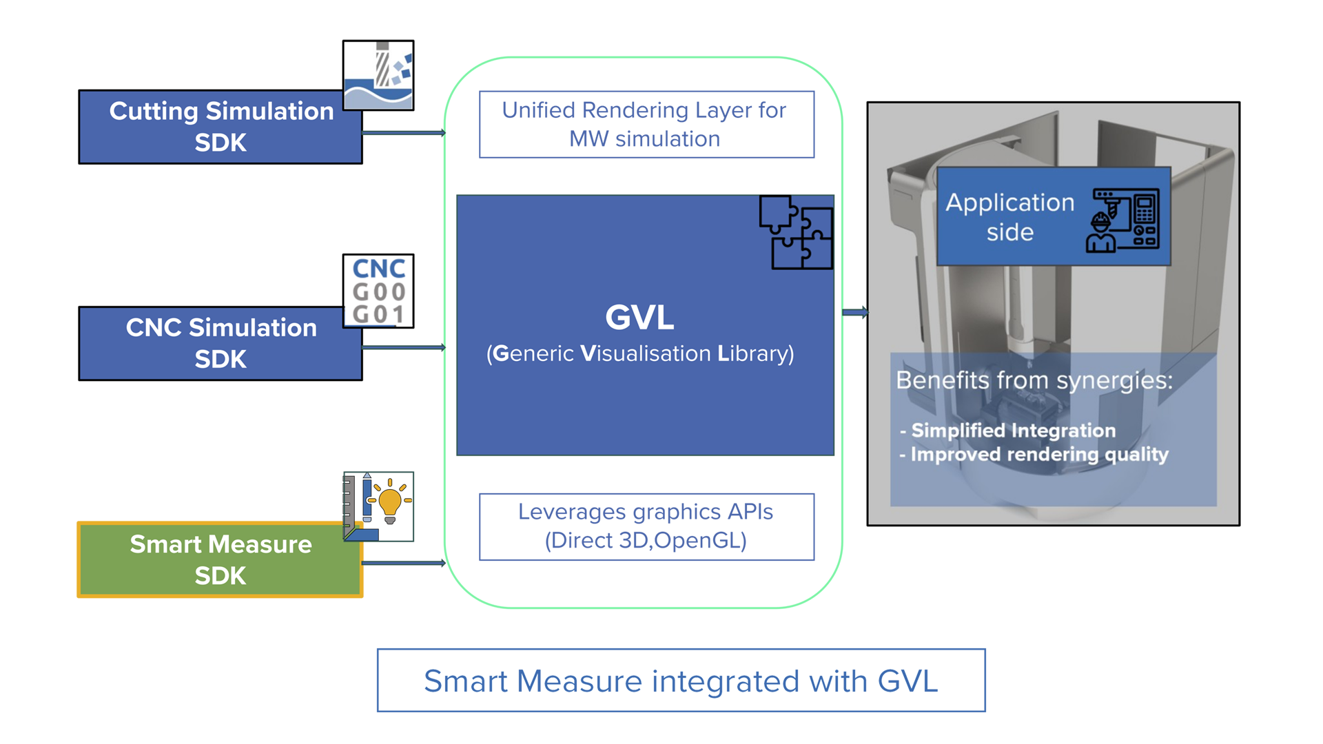
Smart Measure Integrated with Generic Visualization Library
Challenge: In previous versions, the visualization and measurement functionalities had to be integrated individually, which was time consuming and created extra effort for Simulation SDK integrators.
Solution: In previous versions, the visualization and measurement functionalities had to be integrated individually, which was time consuming and created extra effort for Simulation SDK integrators.
Benefits: This new feature simplifies the side-by-side integration of workpiece and machine simulation, enabling consistent measurements across both.
Simulation SDK |
Cutting Simulation
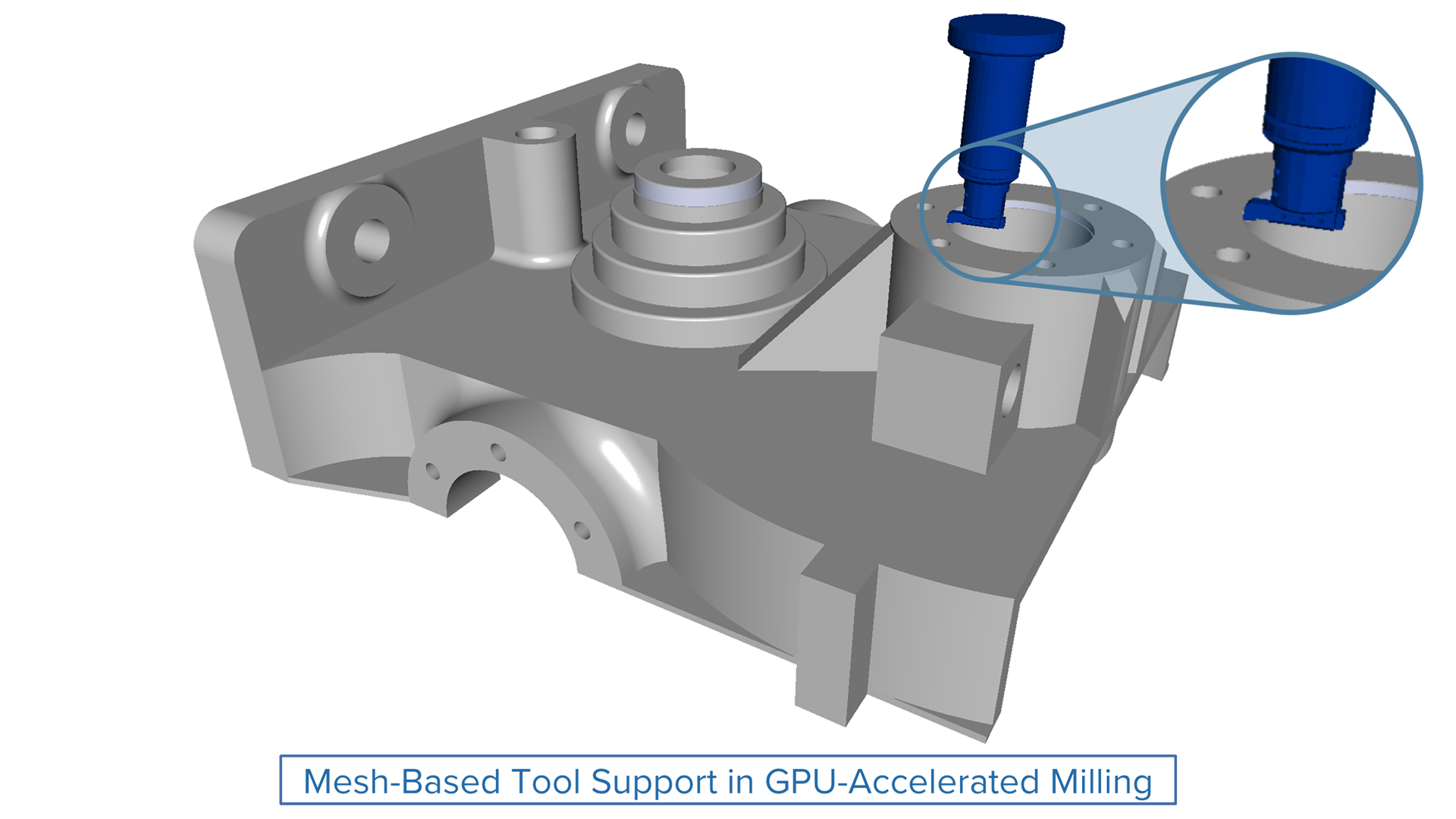
Mesh-Based Tool Support in GPU-Accelerated Milling
Challenge: Previously, GPU‑accelerated simulation only worked with revolved tool shapes, preventing accurate simulation of custom, complex, or asymmetric tool geometries.
Solution: The new mesh‑based tool support within GPU‑accelerated milling allows users to simulate arbitrary 3D tool geometries much faster.
Benefits: This enhancement significantly broadens the applicability of GPU‑accelerated milling, supporting a wider variety of machining scenarios that rely on complex tool shapes.
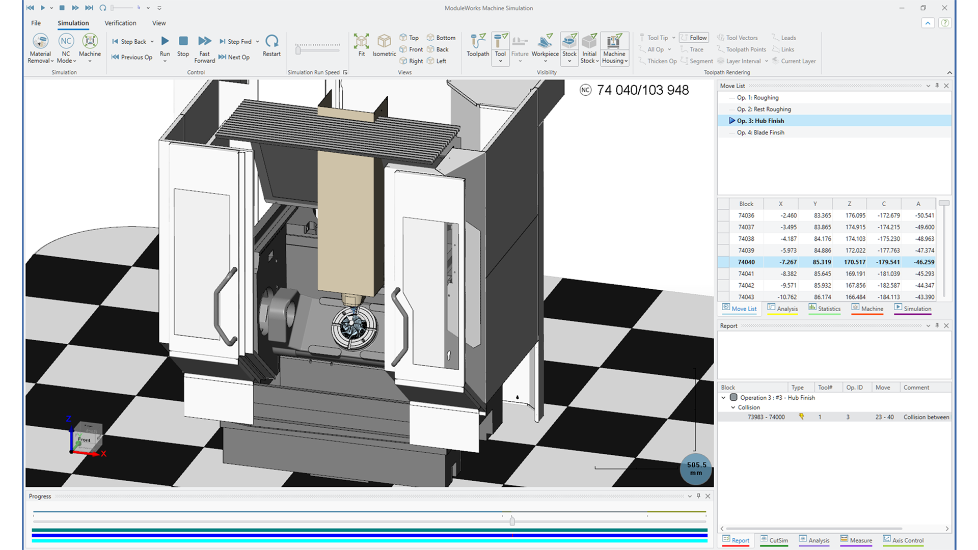
Simulation Systems |
Machine Simulation
Next‑Gen WPF UI
Challenge: The legacy MFC‑based UI limits scalability and no longer meets modern user experience expectations, making it harder to deliver a competitive, polished product.
Solution: Adopt a WPF‑based interface powered by .NET and DirectX that delivers responsive performance, clean XAML architecture and advanced graphics capabilities.
Benefits: A modernized, resolution‑independent UI offers a cleaner, more consistent experience across devices while improving long‑term maintainability and readiness for future enhancements.
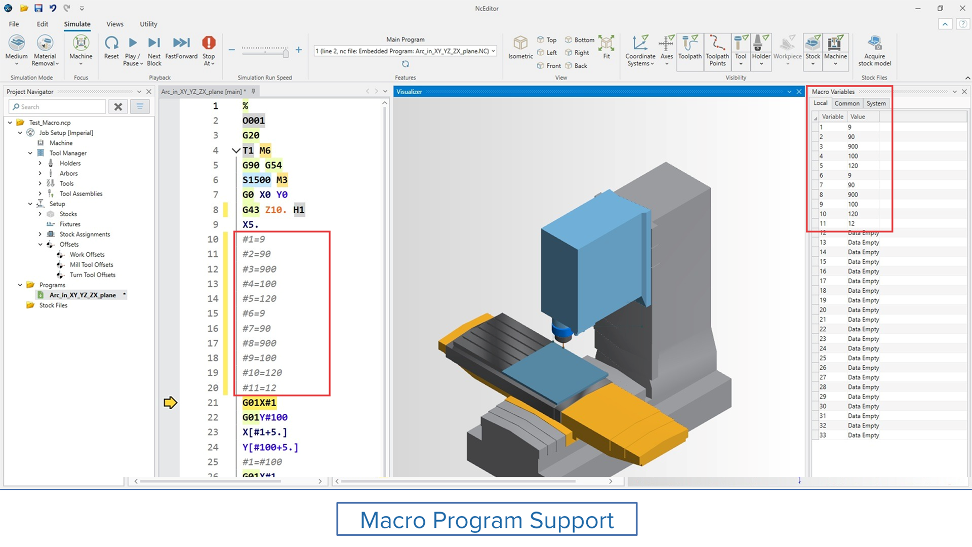
Simulation Systems |
NC Editor
Support for Macro Programs
Challenge: Previously, macro variables couldn’t be used or simulated, limiting the ability to build and validate complex machining logic within the software.
Solution: A new parser enables full support for macro programming, including both local and common variables. Common variables are now stored in the Job Setup, ensuring consistency and reusability across sessions.
Benefits: This enhancement brings greater flexibility and power to G-code programming. Users can now develop, test, and reuse advanced logic with improved control and efficiency.
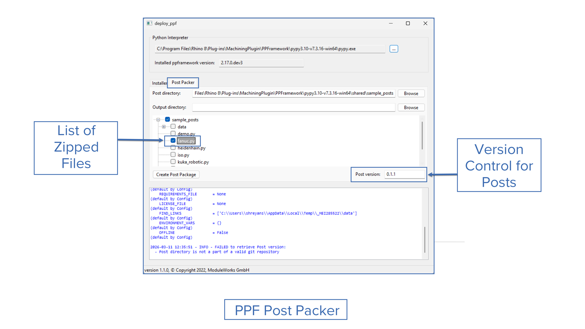
Challenge: Posts developed in-house or by customers must be delivered to end users in the correct format with consistent versioning and clear file contents.
Solution: The new PPF Post Packer enables users to package the right files and supports versioning through Git tags or manual numbers.
Benefits: With PPF Post Packer you can quickly prepare posts in open-source or compiled formats, use Git tags or manual versions to track releases, deploy faster with fewer errors, and deliver clear content for developers and customers.